
Method and facility for assembling components of a vehicle body

a vehicle body and component technology, applied in the direction of resistive welding apparatus, gas flame welding apparatus, soldering auxiliary devices, etc., can solve the problems of not being able to manipulate weights using commercially available heavy-load robots, rigid design of clamping frames,

Inactive Publication Date: 2009-02-26
THYSSENKRUPP DRAUZ NOTHELFER GMBH
View PDF5 Cites 8 Cited by
  • Summary
  • Abstract
  • Description
  • Claims
  • Application Information

AI Technical Summary

Benefits of technology

[0010]The present invention is based on the idea that rigid clamping frames are needed on the geometry box for applying the required clamping forces, but not for the transport of the components to the geometry box. It is therefore sufficient if the side wall part is not grasped over its entire area by the clamping frame during transport. Its weight may then be correspondingly light. This has the result that special transport devices designed for 2000 kg load are not needed for this purpose, but rather the transport may be performed using commercially available heavy load robots. The transport device also no longer has to be dimensioned as sufficiently large for the clamping frame parts to apply the clamping forces during assembly of the components. These forces may, as known per se, be built up by suitable positioning and fixing units which act between the geometry box and the clamping frame parts. A further advantage of the division of the clamping frame for each component into multiple clamping frame parts is that, as a function of the component type, various clamping frame parts (various modules) may be combined with one another. If, for example, for a side wall component, the forward area is identical for various body types, but the rear part differs, various rear clamping frame parts may be combined with the same forward clamping frame part. The positioning of the two clamping frame parts, namely the charged clamping frame part and the empty clamping frame part, preferably occurs in sequence. Using the clamping frame part charged with the component, e.g. a side wall component, this component is pre-positioned on the geometry box and in relation to the component already positioned in the geometry box, e.g. the floor group. The other empty clamping frame part is then guided thereto and the component is fixed thereon in the correct position and attitude. Finally, the final clamping of the clamping frame parts on the geometry box is performed. Because of the successive guiding of the clamping frame parts to the geometry box and the pre-positioning of the clamping frame part first guided to the geometry box, the transport device no longer required for the first clamping frame part may be used to guide the empty clamping frame part thereto.

Problems solved by technology

This means that the clamping frames are designed as very rigid and thus also very heavy.
Such weights may no longer be manipulated using commercially available heavy load robots.

Method used


Image

  • Method and facility for assembling components of a vehicle body
  • Method and facility for assembling components of a vehicle body
  • Method and facility for assembling components of a vehicle body

Examples


Embodiment Construction

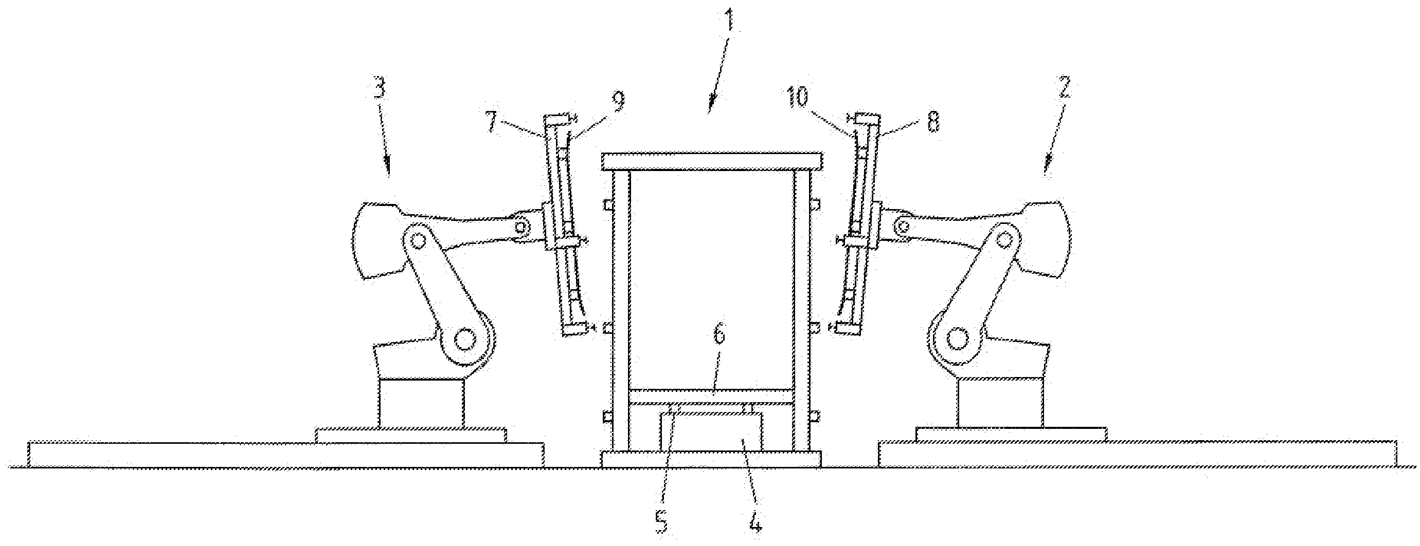
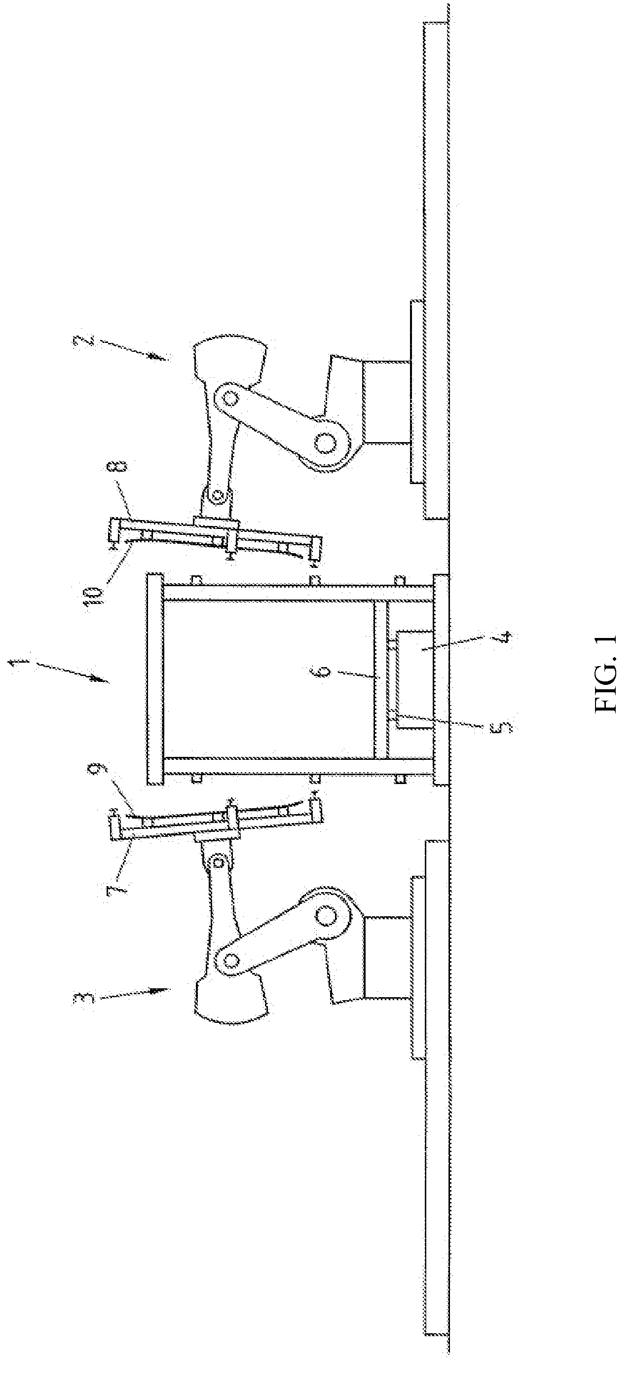
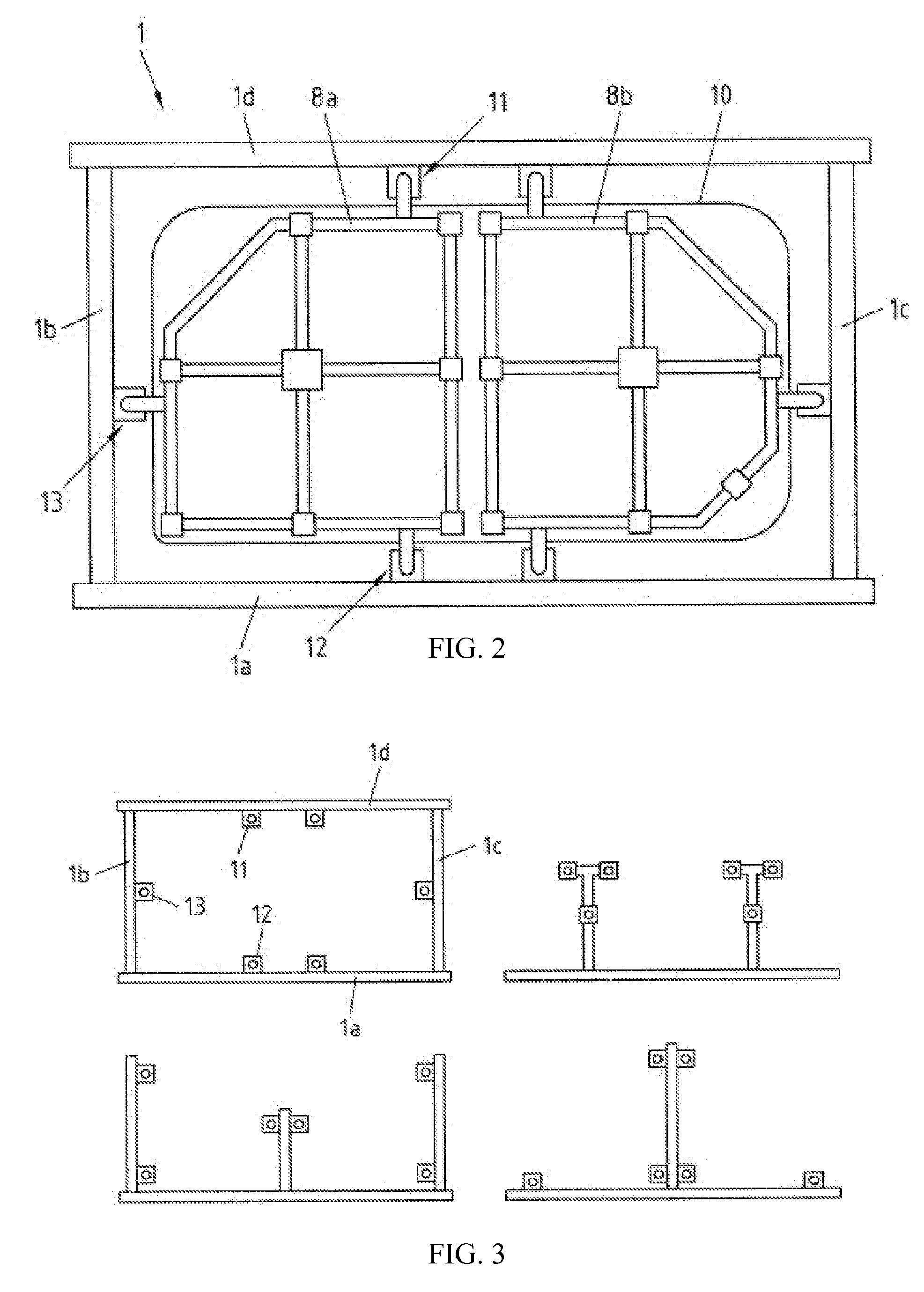
[0017]The facility illustrated in FIG. 1 for assembling components of a vehicle body has a processing station. The processing station comprises a stationary geometry box 1, which is implemented as a frame construction. Various possibilities of the frame construction are shown in a side view in FIG. 3, of which the first exemplary embodiment comprises a floor baseplate 1a, lateral columns 1b, 1c, and a top girder 1d. Furthermore, on both sides of the geometry box 1, the processing station comprises heavy load robots 2, 3 and joining units (not shown), such as welding units, in particular a laser welding apparatus, soldering units, or the like, using which the components of the body to be assembled may be permanently connected to one another by welding.

[0018]A lower construction 4 is located inside the geometry box 1, which may be designed as a clamping frame and on which, using positioning and fixing elements 5, a component 6, in particular the floor group of the vehicle body, may be...


PUM

PropertyMeasurementUnit
lengthaaaaaaaaaa
weightaaaaaaaaaa
weightsaaaaaaaaaa

Abstract

The assembly of body components using a geometry box (1) and clamping frames (7, 8) is described. At least for the larger components (9, 10), in particular the side wall parts of the body, a multipart clamping frame (8a, 8b) is used. The component (9, 10) is grasped and fed to the geometry box (1) using one clamping frame part, while the other clamping frame part is fed empty. Using both clamping frame parts, the component (9, 10) is then fixed precisely in position using positioning and fixing units acting between the geometry box (1) and the clamping frame (7, 8) in such a way that the components (6, 9, 10) to be connected to one another may be connected to one another, in particular welded.

Description

CROSS-REFERENCE TO RELATED APPLICATIONS[0001]This application is a National Phase Application of International Application No. PCT / EP2006 / 061772, filed Apr. 24, 2006, which claims the benefit of and priority to German Application No. 10 2005 027 986.4, filed Jun. 16, 2005, which is owned by the assignee of the instant application. The disclosure of each of the above applications is incorporated herein by reference in its entirety.FIELD OF THE INVENTION[0002]The present invention relates to a method for assembling components of a vehicle body in a processing station having a geometry box having positioning points, in which a component, in particular a floor group, is fixed precisely in position and to which clamping frames, on which the other components, in particular side wall parts, are retained precisely in position and using which they are guided to the geometry box, are clamped in the correct position and attitude in such a way that the components to be connected to one another ...

Claims


Application Information

Patent Timeline
Patent Type & Authority Applications(United States)
IPC IPC(8): B23K31/00B23K37/04
CPCB23K37/04
Inventor GAUGGEL, GERD
Owner THYSSENKRUPP DRAUZ NOTHELFER GMBH
Learn More