Connection diagnostic device and connection diagnostic method for a display

a diagnostic device and display technology, applied in the field of electronic devices, can solve the problems of preventing the functioning of electronic devices, affecting the display, and causing the type of mounting error to occur more easily

Inactive Publication Date: 2012-10-25
DELPHI TECH INC
View PDF3 Cites 5 Cited by
  • Summary
  • Abstract
  • Description
  • Claims
  • Application Information

AI Technical Summary

Benefits of technology

[0013]An advantage of the present invention is that it requires no modification to the connector, to the control board, or to the display and that it does not require a complex external control device. Moreover, the present invention can be implemented at any moment after assembly of the display on the control board.
[0014]In accordance with other advantageous characteristics of the invention: the diagnostic device comprises an electronic control unit which is arranged on the control board; the electronic control unit is formed by the microcontroller that controls the display; the connector is a flexible connector; the flexible connector comprises an alternated succession of electrically conductive strips and electrically insulating strips, orientated parallel with the lateral edges of the flexible connector so that the ends of a conductive strip and the ends of an insulating strip are arranged in alternation along the longitudinal edges of the flexible connector; the electrically insulating strips are made of a flexible plastics material, in particular silicone.
[0015]The invention also proposes interior equipment of a motor vehicle including at least a control knob designed to control an operating parameter of the equipment, characterized by the fact that an electronic device in accordance with one of the preceding characteristics is arranged in the control knob so that the display displays information linked to the operating parameter of the equipment. This equipment forms part for example of a ventilation, heating and / or air-conditioning system.
[0016]The invention also proposes a diagnostic method for an electronic device in accordance with one of the preceding characteristics, the said method being intended to determine the state of connection of the display to the control board. It is characterized by the fact that it includes the following steps: generation of a voltage pulse at at least one connection terminal of the first series, measurement of the electrical voltage at one or more connection terminals associated with the first series, comparison of the measured voltage with a threshold value, emission of a diagnostic signal representative of the state of the connection, the said diagnostic signal being positive when the measured voltage is greater than the threshold value and negative when the measured voltage is lower than the threshold value.
[0017]The method is preferably implemented by means of an electronic control unit which is arranged on the control board. The electronic control unit is formed by the microcontroller that controls the display.
[0018]Further features and advantages will appear more clearly on a reading of the following detailed description of the preferred embodiment, which is given by way of non-limiting example only and with reference to the accompanying drawings.

Problems solved by technology

On assembly of the electronic device, it happens that the flexible connector is badly mounted so that certain connection terminals of the display are not electrically connected to the control board which causes malfunction of the display.
It also happens that the connector and / or the display are overlooked during mounting which prevents any functioning of the electronic device.
This type of mounting error occurs more easily as these mounting operations are generally performed by hand.
However, these detection systems are particularly expensive to implement and they do not allow detection of all mounting errors.
Moreover, these systems do not permit detection of mounting errors after location of the electronic device in the complete equipment, for example in the control panel of a ventilation and heating system.
In this case, the diagnostic of the mounting of the electronic device can only be performed at the end of assembly that in particular excludes the use of detection cameras.

Method used


Image

  • Connection diagnostic device and connection diagnostic method for a display
  • Connection diagnostic device and connection diagnostic method for a display
  • Connection diagnostic device and connection diagnostic method for a display

Examples


Embodiment Construction

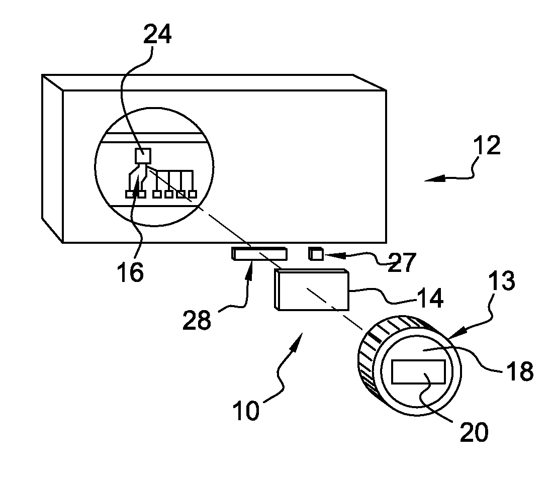
[0025]FIG. 1 shows an electronic device 10 in accordance with a preferred embodiment of the invention. In accordance with this embodiment, the electronic device 10 is a display device which is arranged in interior equipment of the motor vehicle 12, in particular in a control panel 12 belonging to a ventilation, heating and / or air-conditioning apparatus. More particularly, the display device 10 is associated with a rotary control knob 13 for controlling an operating parameter of the apparatus such as the interior temperature of the vehicle.

[0026]The display device 10 includes a liquid crystal display 14 and a control board 16 for operating the display 14. In accordance with the embodiment shown, the display 14 is mounted inside a fixed part 18 of the rotary control knob to be visible to a user through a suitable window 20.

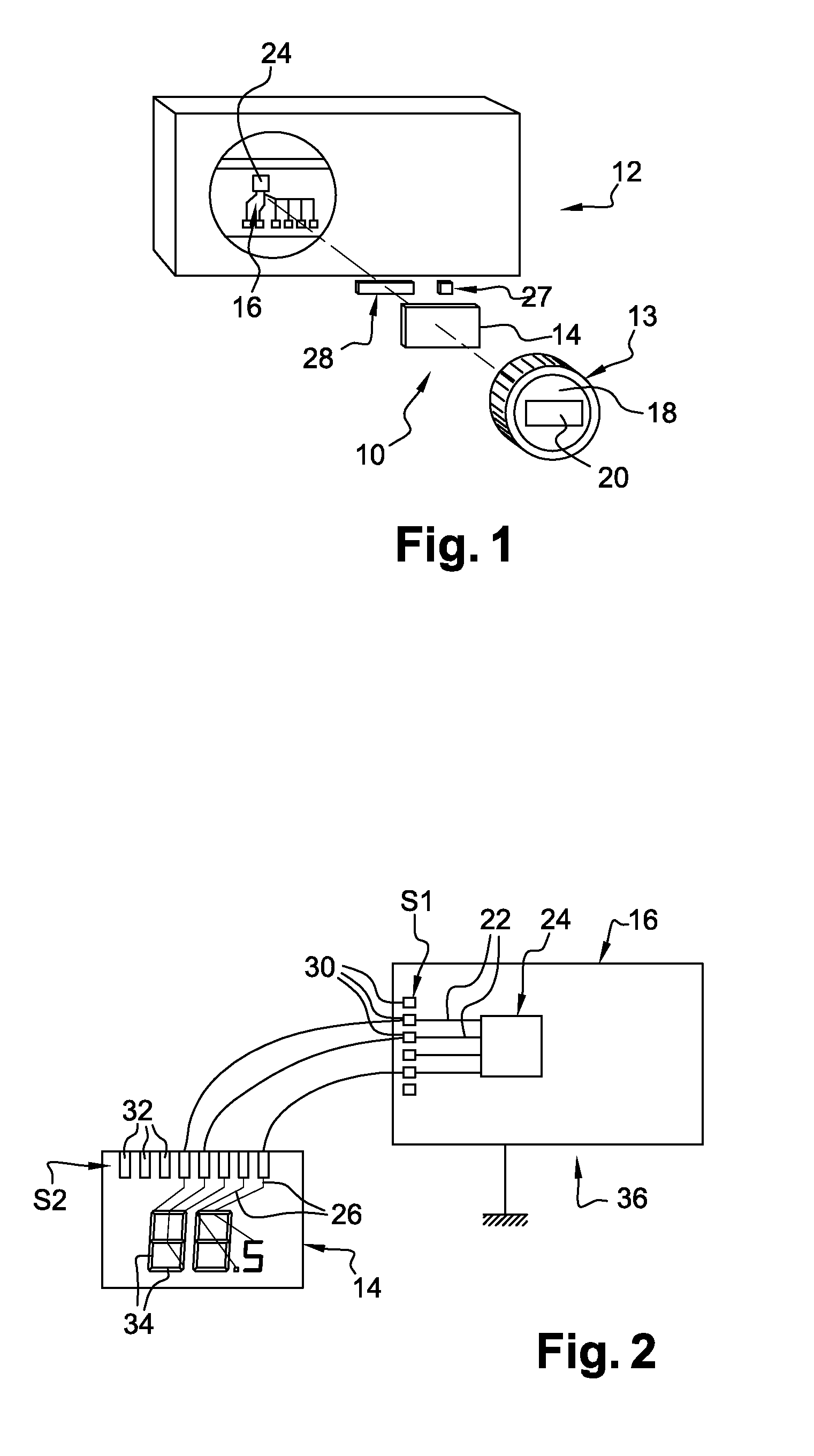
[0027]The control board 16 is here mounted on a fixed support within the control panel 12. It includes electrical tracks 22 shown diagrammatically in FIG. 2, which ...


PUM


Abstract

An electronic device comprising a liquid crystal display and a control board, the electrical tracks of the board and of the display being connected by a connector, the control board including a microcontroller able to apply an electrical voltage to at least one connection terminal in order to display given information on the display, characterised by the fact that the control board includes a diagnostic device which is designed to generate a voltage pulse at connection terminals and to measure the resulting electrical voltage in order to determine the state of the connection between the display and the board as a function of the value of the measured electrical voltage.

Description

CROSS-REFERENCE TO RELATED APPLICATION[0001]This application claims the benefit under 35 U.S.C. §371 of published PCT Patent Application No. PCT / EP 2010 / 068325, filed Nov. 26, 2010, and was published as WO2011 / 073014A1 on Jun. 23, 2011, the entire contents of which is hereby incorporated by reference herein.TECHNICAL FIELD OF INVENTION[0002]The present invention relates to an electronic device provided with a liquid crystal display in particular intended to be installed on a structural element of a motor vehicle. The present invention also relates to a diagnostic method of the state of connection of the display.BACKGROUND OF INVENTION[0003]In the motor vehicle field, it is usual to provide a vehicle with an electronic device including two electronic components connected to each other by a flexible connector. Such a device is, for example, an information display device which is intended to be installed on a structural element of the vehicle, such as a dashboard, a console, or the lik...

Claims


Application Information

Patent Timeline
Patent Type & Authority Applications(United States)
IPC IPC(8): G09G3/36G06F3/038
CPCG09G3/006H01R13/2414H01R12/55G09G3/04
Inventor WICKY, HERVETIHAY, DAVID
Owner DELPHI TECH INC
Why Eureka
Try Eureka