Frac-pack casing saver

a frac-pack and casing technology, applied in the direction of fluid removal, earthwork drilling and mining, borehole/well accessories, etc., can solve the problems of not being desirable, fluid velocity, filter cake on the wellbore wall falling off, etc., to prevent or minimize direct impingement, simply repla

Inactive Publication Date: 2009-07-14
BAKER HUGHES HLDG LLC
View PDF8 Cites 77 Cited by
  • Summary
  • Abstract
  • Description
  • Claims
  • Application Information

AI Technical Summary

Benefits of technology

[0005]A deflection device keeps high velocity gravel slurry flow from directly impinging the wellbore wall in open hole and breaking loose the filter cake coating on the wall or, in a cased hole, prevents the direct impingement of gravel slurry on the casing which can cause wear from erosion. The slurry exist from an intermediate annulus in a crossover that is fitted with movable members that can be pivotally mounted for rotational displacement by the pumped slurry to act as a deflector to prevent or minimize direct impingement on the wellbore wall or casing. When the flow stops the deflectors can pivot back to their original positions. The deflectors can be simply replaced when worn.

Problems solved by technology

Additionally, if the well is open hole, the high fluid velocities make the filter cake on the wellbore wall come off.
This is also not desirable as the gravel and fluid would tend to go into the formation at that location rather than further along the wellbore.
Alternatively the filter cake can plug the gravel pack and impede subsequent production.

Method used


Image

  • Frac-pack casing saver
  • Frac-pack casing saver
  • Frac-pack casing saver

Examples


Embodiment Construction

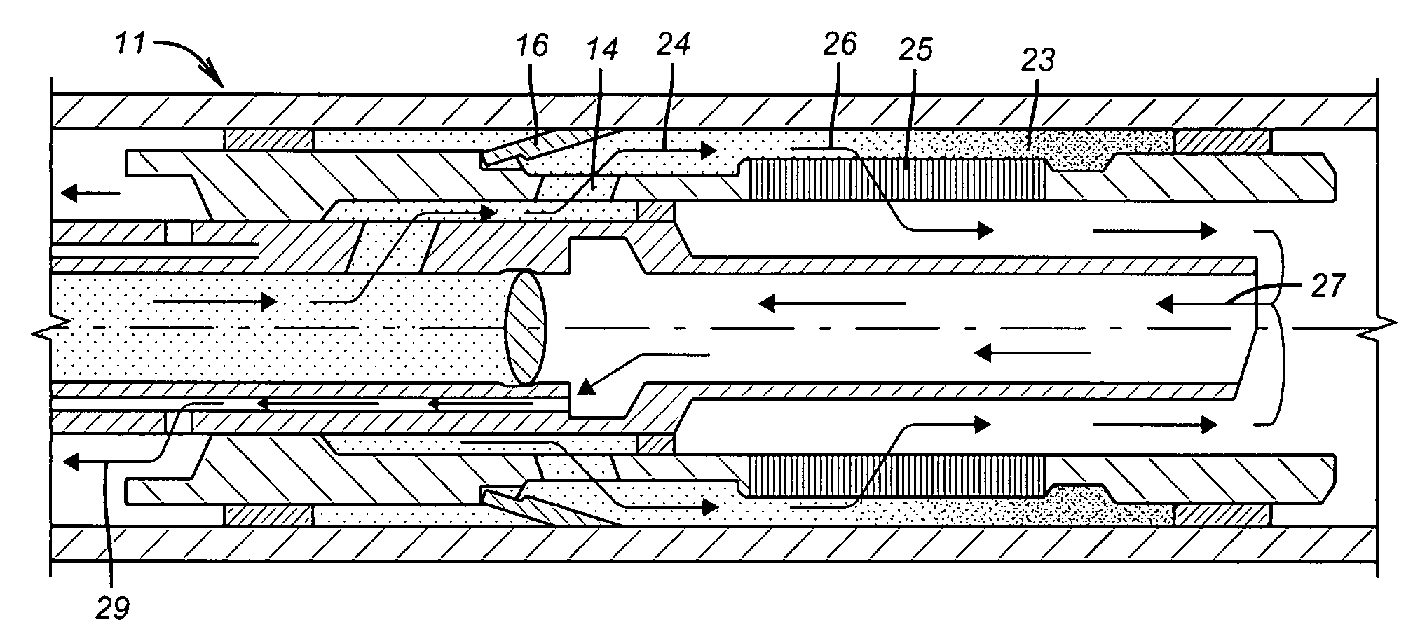
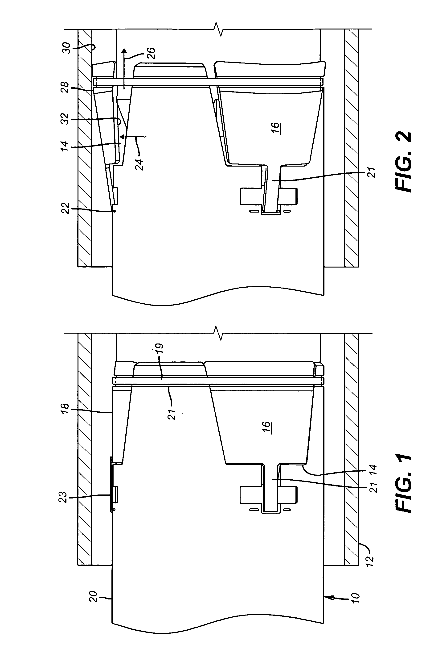
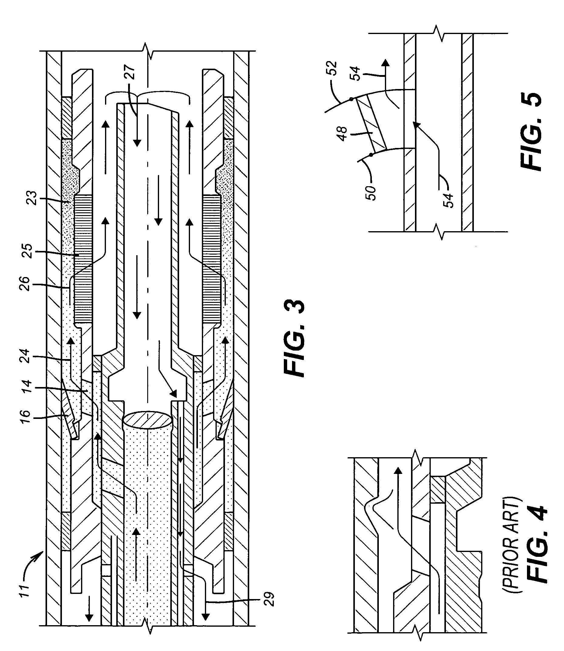
[0011]FIG. 1 illustrates a tubular shape 10 that defines the inner annulus from a crossover 11 shown in FIG. 3, through which the gravel slurry travels after coming down a tubing string (not shown) and through a packer (not shown). These components are omitted because they are well known to those skilled in the art and the Figures focus on the modification to such equipment that addresses the issue of erosion of a surrounding casing or wellbore, either of which is shown as 12 surrounding the tubular 10. Tubular 10 has one or a plurality of outlets 14 that are normally covered, when there is no slurry flow through the crossover, by deflection members 16. Preferably members 16 on their outer surface 18 take the curvature of the tubular 10 so that surface 18 becomes approximately the continuation of the outer surface 20 of the tubular 10. Deflection or diverter member 16 is preferably pivotally mounted at pin 22 that is more easily seen in FIG. 2. It can have a generally trapezoidal sh...


PUM


Abstract

A deflection device keeps high velocity gravel slurry flow from directly impinging the wellbore wall in open hole and breaking loose the filter cake coating on the wall or, in a cased hole, prevents the direct impingement of gravel slurry on the casing which can cause wear from erosion. The slurry exist from an intermediate annulus in a crossover that is fitted with movable members that can be pivotally mounted for rotational displacement by the pumped slurry to act as a deflector to prevent or minimize direct impingement on the wellbore wall or casing. When the flow stops the deflectors can pivot back to their original positions. The deflectors can be simply replaced when worn.

Description

FIELD OF THE INVENTION[0001]The field of this invention relates to gravel delivery systems involving crossovers where the delivery rates are elevated to compensate for highly unconsolidated formations.BACKGROUND OF THE INVENTION[0002]Gravel packing is the technique of depositing proppant or sand in perforations to promote production and to slow the production of particulates from the formation as the hydrocarbons are produced. In the case of unconsolidated formation with relatively high permeability, much of the fluid used to circulate the gravel can be absorbed by the formation when gravel is delivered. To compensate for this fluid loss and to be able to also frac the formation as the gravel is delivered, the pumping rate has been greatly stepped up. While operations in more consolidated formations could result in an adequate frac job with about 15 barrels a minute flow rate, flow rates in the order of 65 barrels per minute or more are not unusual when dealing with a fairly unconso...

Claims


Application Information

Patent Timeline
Patent Type & Authority Patents(United States)
IPC IPC(8): E21B43/04
CPCE21B43/267E21B43/045
Inventor CLEM, NICHOLAS J.
Owner BAKER HUGHES HLDG LLC
Why Eureka
Try Eureka