Flow meter

a flow meter and flow rate technology, applied in the direction of instruments, volume/mass flow by dynamic fluid flow effect, measurement devices, etc., can solve the problems of increased flow resistance, reduced inner diameter, pressure loss, etc., and achieve safe and reliable flow velocity.

Active Publication Date: 2020-01-16
SIKA DR SIEBERT & KÜHN GMBH & CO KG
View PDF0 Cites 0 Cited by
  • Summary
  • Abstract
  • Description
  • Claims
  • Application Information

AI Technical Summary

Benefits of technology

[0007]The object of the invention is the improvement of a flow meter for measuring the flow velocity of a fluid that is...

Problems solved by technology

A further disadvantage comprises the measuring tube having a reduced inner diameter due to the inserted insertion tube, whereby pressure losses arise and the flow resistance increases.
A disadvantage of this embodiment comprises the structure of the measuremen...

Method used


Image

  • Flow meter
  • Flow meter
  • Flow meter

Examples


Embodiment Construction

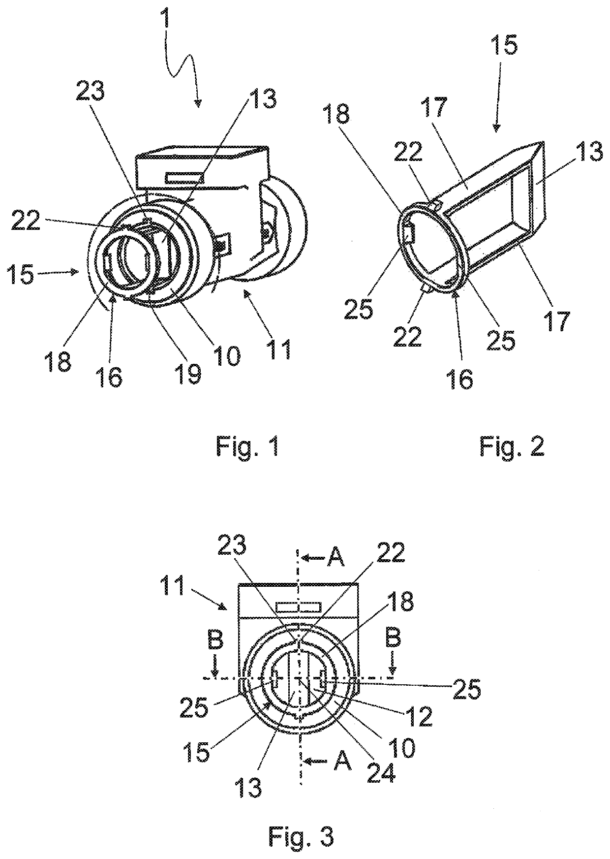
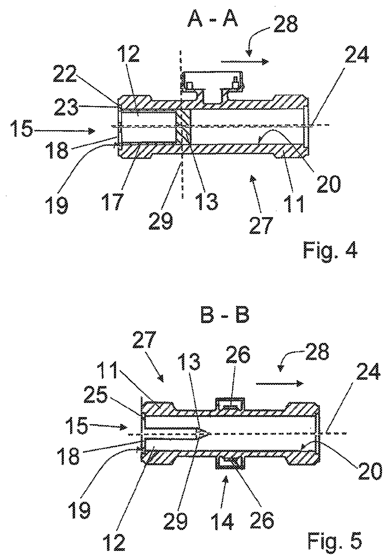
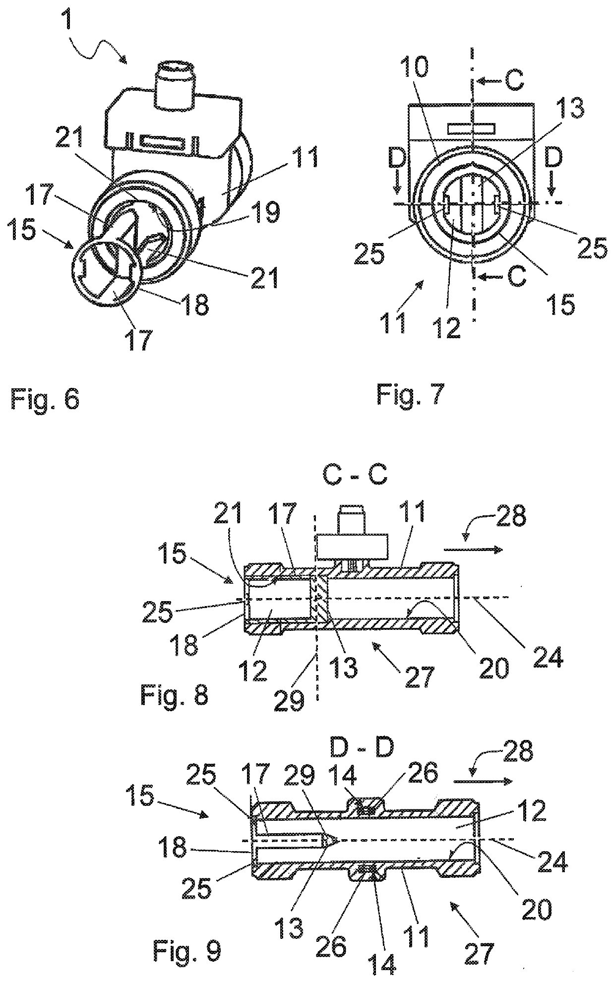
[0029]FIG. 1 shows in a perspective representation a flow meter 1 having a flange end 10 formed at a measurement tube 11. An insertion element 15 is partially inserted into the measurement tube 11 at the flange end side. The insertion element 15 comprises a base portion 16 formed as an annular member 18 and having two moldings 22 and also comprises a baffle 13. The baffle 13 is here located in the measurement tube 11. An annular groove 19 for receiving the annular member 18 and cutouts 23 for receiving the complementary moldings 22 are arranged at the flange end 10.

[0030]The insertion element 15 is shown in FIG. 2 comprising the base portion 16 configured as the annular member 18 and having brackets 17 arranged thereat between which the baffle 13 is formed. Projections 25 are radially inwardly formed at diametrically opposed sides at the annular body. Radially outwardly projecting moldings 22 are furthermore formed at the annular member 18.

[0031]The measurement tube 11 is shown with...


PUM


Abstract

A flow meter for measuring the flow velocity of a fluid includes a measurement tube that is axially bounded by at least one flange end and that forms a measurement space that can be flowed through by the fluid. At least one baffle is provided for generating interference in the flow, wherein the baffle is arranged in the measurement space. A detector for detecting the interference is arranged downstream of the baffle. An insertion element is introduced into the measurement tube and has a base portion. The base portion is arranged in the flange end. The insertion element has brackets that adjoin the base portion and that project into the measurement space, with the baffle being formed and its position in the measurement space being held between the brackets.

Description

CROSS-REFERENCE TO RELATED APPLICATION[0001]This application claims priority of German Patent Application DE 10 2018 116 640.0 filed Jul. 10, 2018, the entire content of which is incorporated herein by reference.FIELD OF THE INVENTION[0002]The invention relates to a flow meter for measuring the flow velocity of a fluid having a measurement tube that is axially bounded by at least one flange end and that forms a measurement space that can be flowed through by the fluid and having at least one baffle to generate interference in the flow, wherein the baffle is arranged in the measurement space and wherein a detector for detecting the interference is furthermore arranged downstream of the baffle.BACKGROUND OF THE INVENTION[0003]A flow meter is known from EP 1 967827 A1 for measuring the flow velocity of a fluid having a measurement tube and having an insertion tube that is inserted into the measurement tube and that forms a measurement space that can be flowed through by the fluid and h...

Claims


Application Information

Patent Timeline
IPC IPC(8): G01F1/32
CPCG01F1/3209G01F1/3281G01P5/01G01F1/3218G01F1/3259
Inventor KETELSEN, JÖRN-OVEBLEICHERT, BASTIANSCHMIDT, SERGIUS
Owner SIKA DR SIEBERT & KÜHN GMBH & CO KG
Why Eureka
Try Eureka