
Milk meter

a technology of milk meter and connector, which is applied in the field of milk meter, can solve the problems of typical connectors, and achieve the effect of stable milk surface and little “undulation”

Active Publication Date: 2018-05-01
N V NETHERLANDSCHE APPNFAB NEDAP
View PDF11 Cites 0 Cited by
  • Summary
  • Abstract
  • Description
  • Claims
  • Application Information

AI Technical Summary

Benefits of technology

The invention is a milk meter that uses wireless technology to measure the flow rate of milk. This eliminates the need for cables, which can be long and sensitive to moisture. The electronic measuring unit is protected from contamination and external magnetic fields. The measuring chamber is connected to a buffer reservoir, which ensures a stable milk surface and reduces bobbing of the float. The buffer reservoir has an outflow opening that increases in size with increasing flow rate, allowing for proper division between the level of the milk in the reservoir and the flow rate. The bottom of the buffer reservoir and the fluid connection are at the same height, providing a stable milk surface and reducing bobbing of the float. The technical effects of this invention include improved accuracy in measuring the flow rate of milk, reduced wear on the moving parts, and improved protection against external contamination.

Problems solved by technology

A further disadvantage of the use of cables is that they are typically provided with connectors which are sensitive to moisture.

Method used


Image

  • Milk meter
  • Milk meter
  • Milk meter

Examples


Embodiment Construction

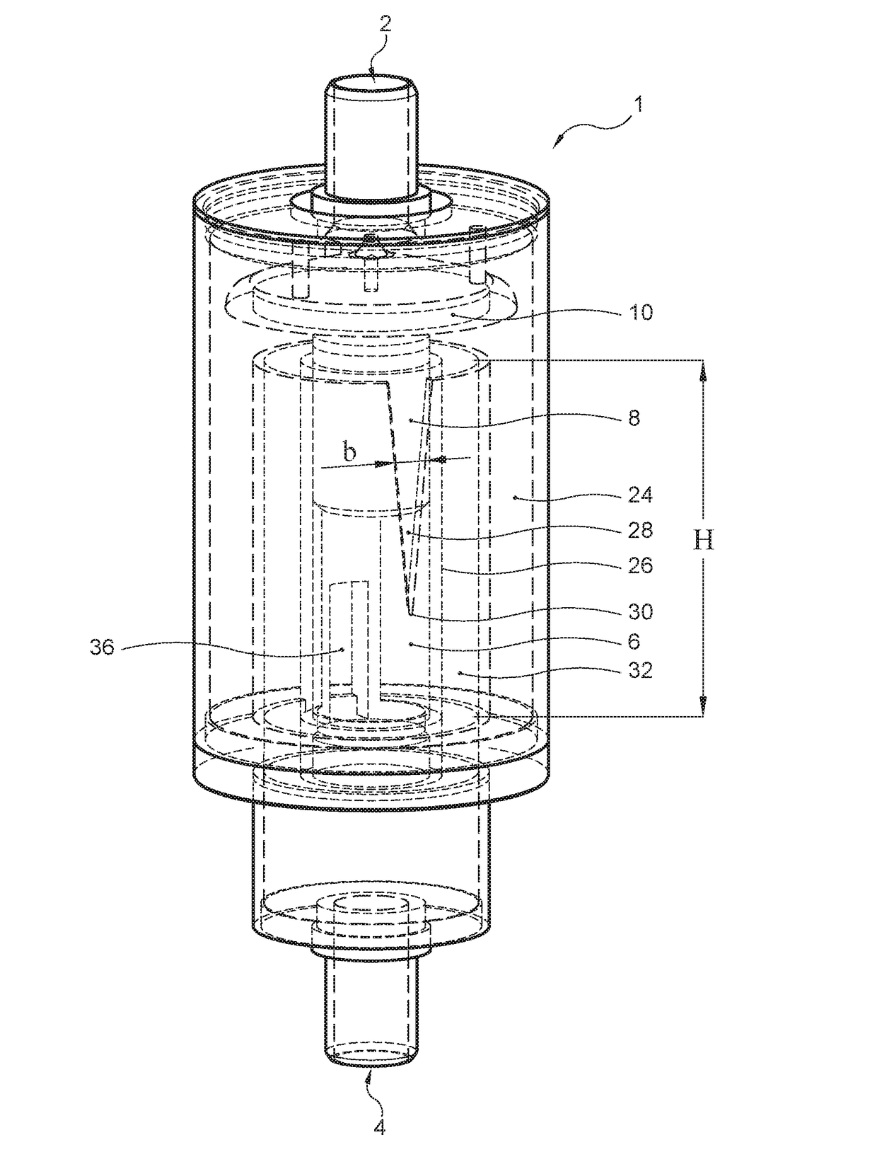
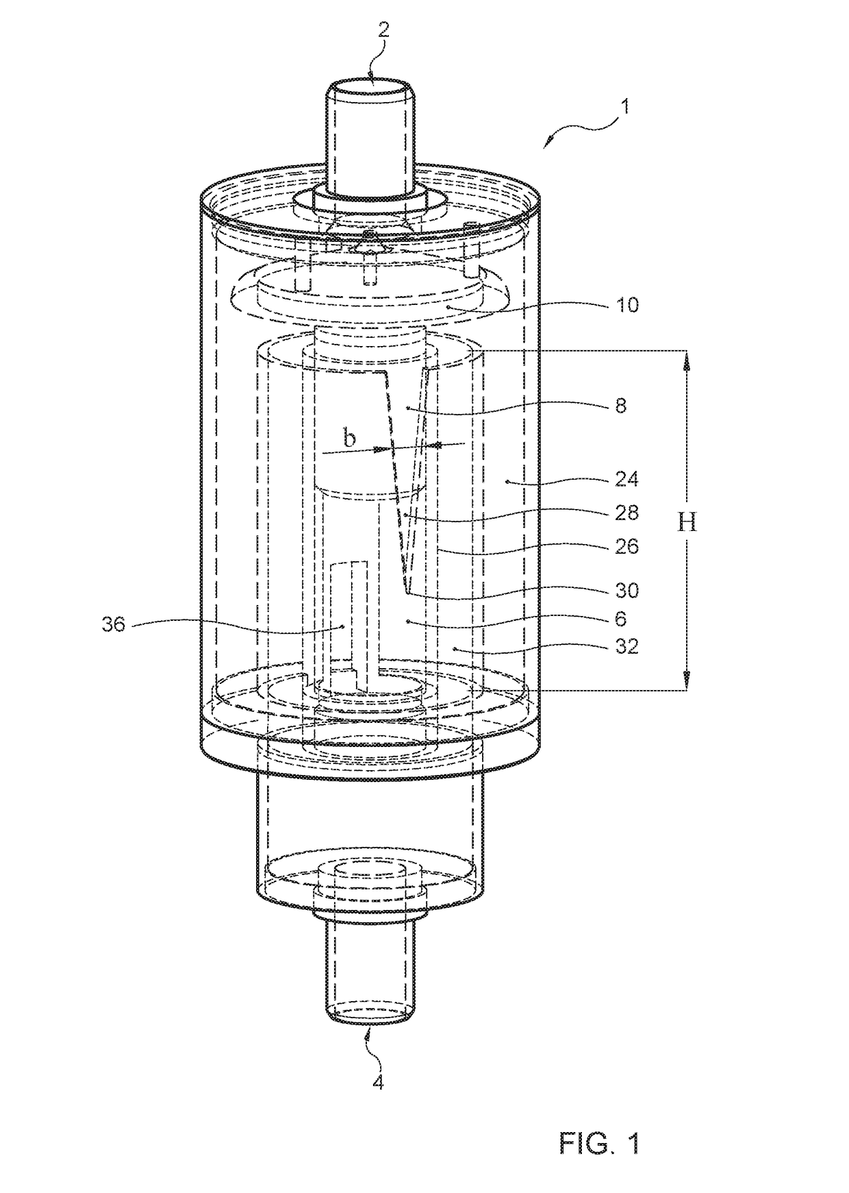
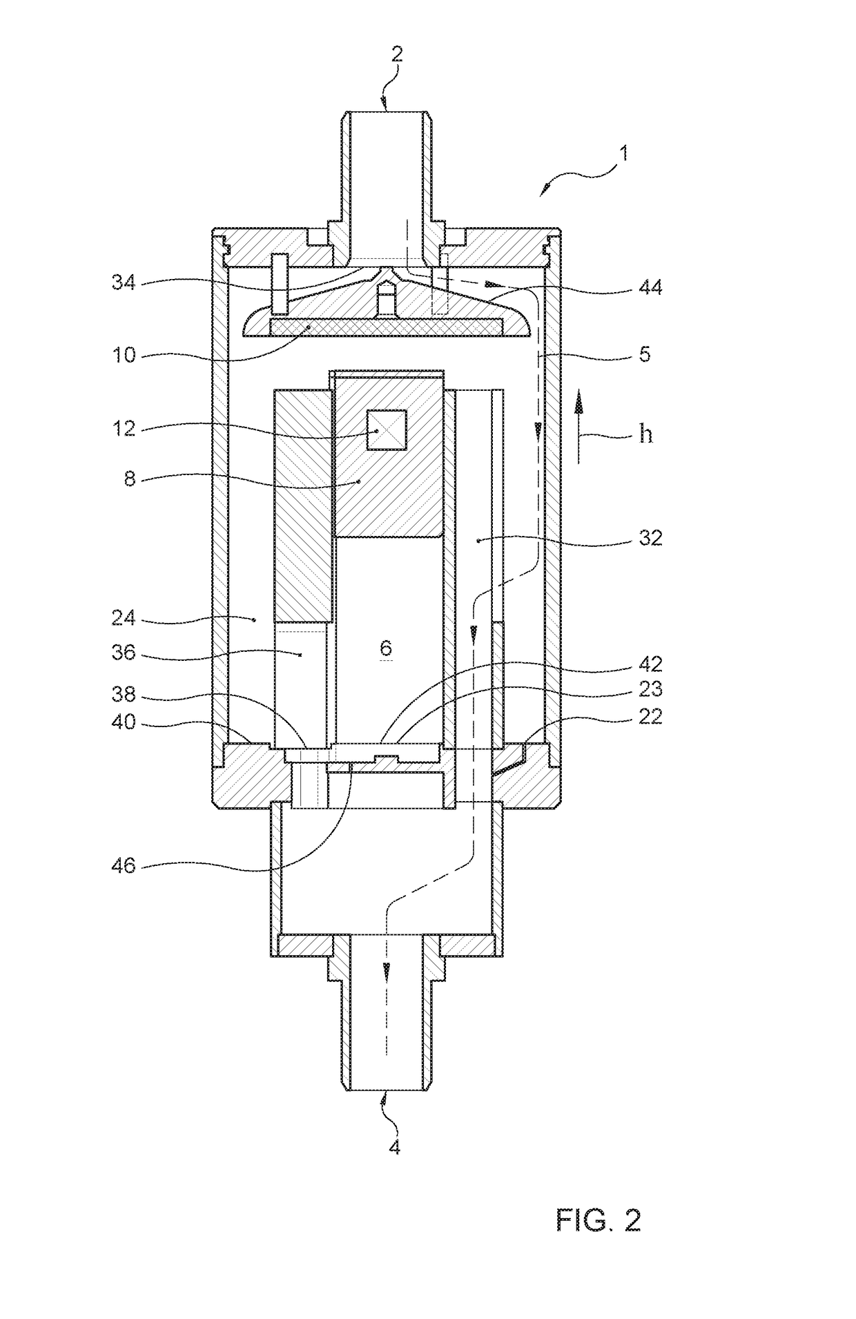
[0023]In FIG. 1, with reference numeral 1 a possible embodiment of a milk meter according to the invention is indicated. The milk meter is provided with an inlet 2 into which, in use, the milk flow whose flow rate is to be measured is supplied. Further, the milk meter is provided with an outlet 4 where the milk flow whose flow rate has been measured, in use, leaves the milk meter again. Between the inlet and the outlet extends a liquid flow path 5 which is schematically indicated in the drawing with a broken line. Obviously, the broken line concerns just one possible pathway along which the milk flow can proceed; reason why the representation is schematic.

[0024]The milk meter is provided with a measuring chamber 6 which is included in the liquid flow path 5. The milk meter is furthermore provided with a float 8 which is in the measuring chamber and which is configured to float on the milk of the milk flow that, in use, is in the measuring chamber. The milk meter is configured such t...


PUM


Abstract

Milk meter for measuring a flow rate of a milk flow, provided with an inlet, an outlet, and a liquid flow path from the inlet to the outlet. The milk meter has a measuring chamber and a float in the measuring chamber configured to float on milk. The milk meter determines the flow rate from the level of milk and the milk meter is provided with a magnetic unit for generating a magnetic field and the magnetic field varies in height direction of the measuring chamber, and the float has an electronic measuring unit for measuring the strength of the magnetic field. The measured strength of the magnetic field is a measure of the height at which the float is floating on the milk and the measured strength of the magnetic field is a measure of the flow rate of the milk flow.

Description

BACKGROUND OF THE INVENTION[0001]The invention relates to a milk meter for measuring a flow rate of a milk flow, provided with an inlet to which, in use, the milk flow is supplied, an outlet where the milk flow leaves the milk meter, in use, and a liquid flow path extending from the inlet to the outlet.[0002]Such milk meters, of diverse types, are known. Many known milk meters are mechanical fill and dump meters, which contain moving parts. A drawback of such mechanical milk meters is that the moving parts are subject to wear and require maintenance, and further are susceptible to pollution. The invention contemplates the provision of a milk meter that contains an improvement over known milk meters.CROSS-REFERENCE TO RELATED APPLICATIONS[0003]“Not Applicable”STATEMENT REGARDING FEDERALLY SPONSORED RESEARCH OR DEVELOPMENT[0004]“Not Applicable”THE NAMES OF THE PARTIES TO A JOINT RESEARCH AGREEMENT[0005]“Not Applicable”STATEMENT REGARDING PRIOR DISCLOSURES BY THE INVENTOR OR A JOINT IN...

Claims


Application Information

Patent Timeline
Patent Type & Authority Patents(United States)
IPC IPC(8): G01F1/52G01F1/00A01J5/01
CPCG01F1/52G01F1/007A01J5/01
Inventor VAN DIJK, JEROEN MARTIN
Owner N V NETHERLANDSCHE APPNFAB NEDAP
Learn More