Milk meter

a technology of milk meter and connector, which is applied in the field of milk meter, can solve the problems of typical connectors, and achieve the effect of stable milk surface and little “undulation”

Active Publication Date: 2017-04-27
N V NETHERLANDSCHE APPNFAB NEDAP
View PDF8 Cites 9 Cited by
  • Summary
  • Abstract
  • Description
  • Claims
  • Application Information

AI Technical Summary

Benefits of technology

[0008]An advantage of the milk meter according to the invention is that the moving float is not subject to wear because measuring is done contactlessly and the obtained information about the flow rate is emitted wirelessly. The ability to transmit information about the measured flow rate wirelessly moreover provides the advantage that a lot of cable can be saved. in large cow houses this can easily run up to kilometers of cable. This is because an udder of the cow has to be freely accessible, which is why cables are mostly diverted along a direction of a path along which the cows walk in the milking parlor, so that the cows cannot come into contact with the cables. A further disadvantage of the use of cables is that they are typically provided with connectors which are sensitive to moisture. Especially a milking parlor is particularly moist. This makes it particularly advantageous when the electronic measuring unit is provided with a transmitter unit as has been indicated above.
[0009]A further advantage is that the vulnerable electronic measuring unit is included in the float, and hence can be well protected from contamination and other interactions with, for example, objects from outside of the milk meter. Moreover, it appears that in this manner the flow rate of the milk flow can be determined very accurately. A reason for this is that the float lowers through foam floating on the milk. As a result, a measurement is performed where the foam does not introduce any inaccuracy in the measurement. As the electronic measuring unit is in the float, the weight of a float can be kept small. Consequently, the float itself can also be kept small. In particular, it holds that the milk meter is furthermore provided with a magnetic unit for generating a magnetic field in the measuring chamber such that the magnetic field varies in a height direction of the measuring chamber, wherein the electronic measuring unit is configured for measuring the strength of the magnetic field, wherein the measured magnetic field strength of the magnetic field is a measure of the height within the measuring chamber at which the float is floating on the milk in the measuring chamber and whereby hence the measured field strength of the magnetic field is a measure of the flow rate of the milk flow. In this manner, the height at which the float is in the measuring chamber can be accurately measured. In particular, it holds that a magnetic unit is provided with a permanent magnet. The permanent magnet has as an advantage that it is also insensitive to the environment of the milking parlor. As it has been chosen to arrange the electronic measuring unit in the float, instead of the permanent magnet, the float, as mentioned, can be kept light and hence relatively small. Moreover, this way the magnet can be of relatively large design. A large magnet provides that with the aid of the electronic measuring unit measuring can be done in a low-energy manner. Moreover, no, or hardly any, disturbance due to external magnetic fields or even the geomagnetic field occurs. The float can be of exchangeable design so that the electronics can be easily upgraded. In particular, it holds that the electronic measuring unit is provided with a supply. While, as mentioned, the electronic measuring unit can work in a low-energy manner, in this way the float can still be simply replaced when the supply is empty.
[0012]More particularly, it holds according to a preferred embodiment that the milk meter is provided with a buffer reservoir which is included upstream of the measuring chamber in the liquid flow path, while in a sidewall of the buffer reservoir an outflow opening is provided which extends from a lowest point of the outflow opening upwardly and which is in fluid communication with the outlet, while a top of the buffer reservoir comprises an inlet opening which is in fluid communication with the inlet, and wherein the buffer reservoir and the measuring chamber are connected with each other via a fluid communication connection, briefly: fluid connection, such that the buffer reservoir, fluid connection and measuring chamber, in use, function as communicating vessels so that, in use, a level of the milk in the measuring chamber is equal to a level of the milk in the buffer reservoir. It appears that in this manner a very reliable measurement can be performed which works well with both relatively high flow rates and relatively low flow rates.
[0013]In particular, it holds here that the outflow opening of the buffer reservoir has a width that increases in upward direction. This has as a consequence that with an increasing flow rate the milk flow through the outflow opening can easily increase so that a proper division can be obtained between on the one hand a level of the milk in the buffer reservoir and on the other hand the flow rate of the milk flow.
[0016]According to a preferred embodiment, it further holds that a bottom of the buffer reservoir and a bottom of the fluid connection are at a same height as a bottom of the measuring chamber. The milk flow being distributed by a plate leads to a quiet depositing of the milk flow in the buffer reservoir. This provides the advantage that a stable milk surface is obtained with little “undulation”. This in turn provides the advantage that bobbing of the float is counteracted. In particular, the measuring chamber 6, the buffer reservoir 24, the bypass channel 32 and the fluid connection 36 are of a non-magnetizable material such as plastic or aluminum.

Problems solved by technology

A further disadvantage of the use of cables is that they are typically provided with connectors which are sensitive to moisture.

Method used


Image

  • Milk meter
  • Milk meter
  • Milk meter

Examples


Embodiment Construction

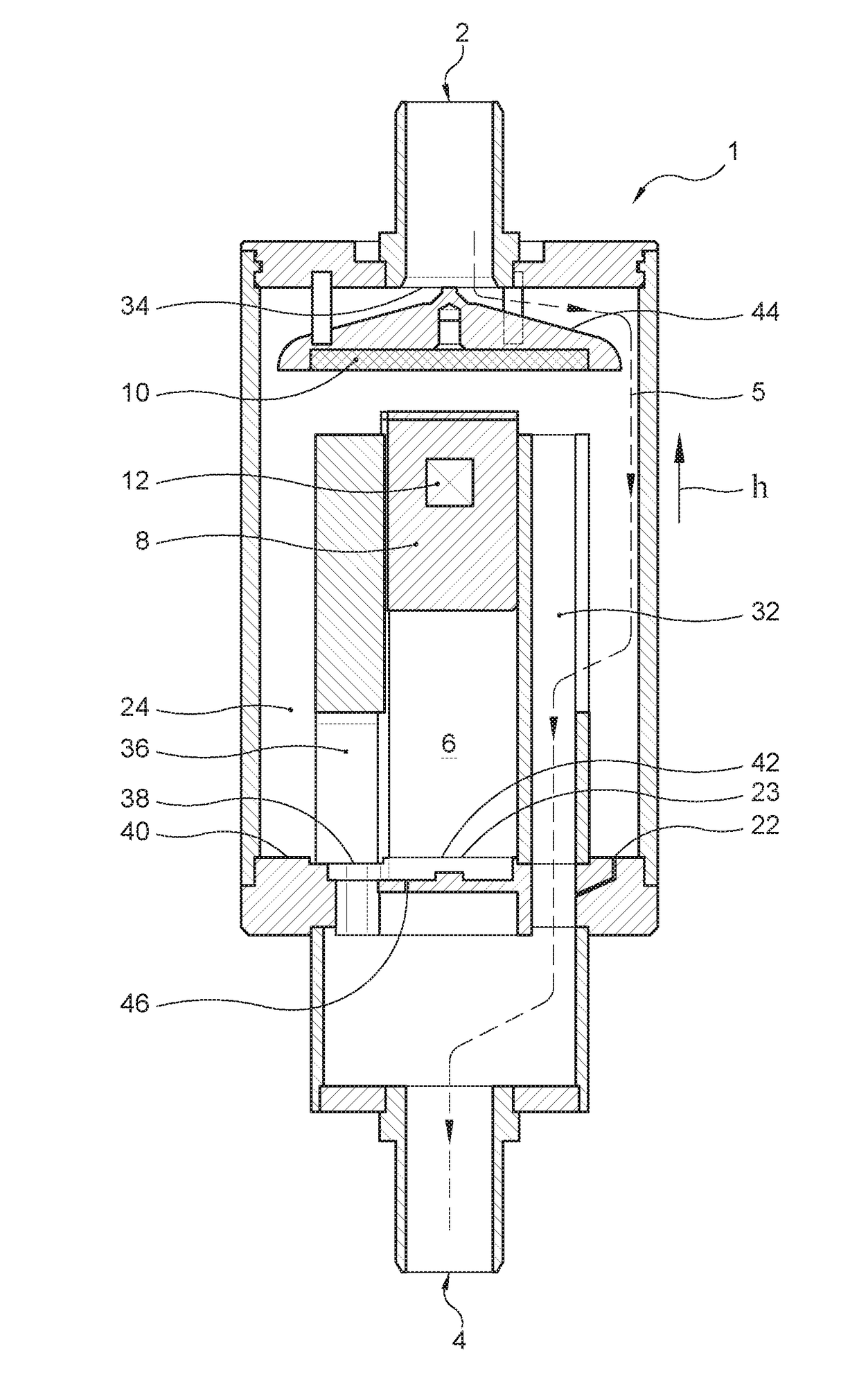
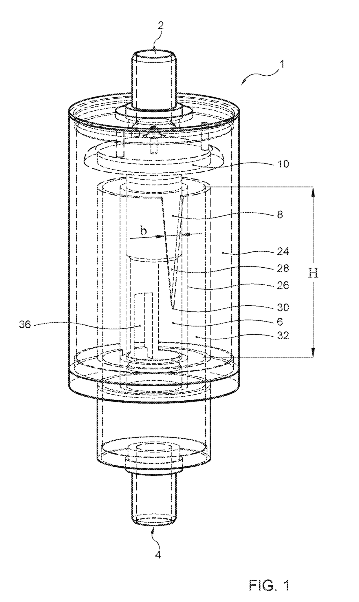
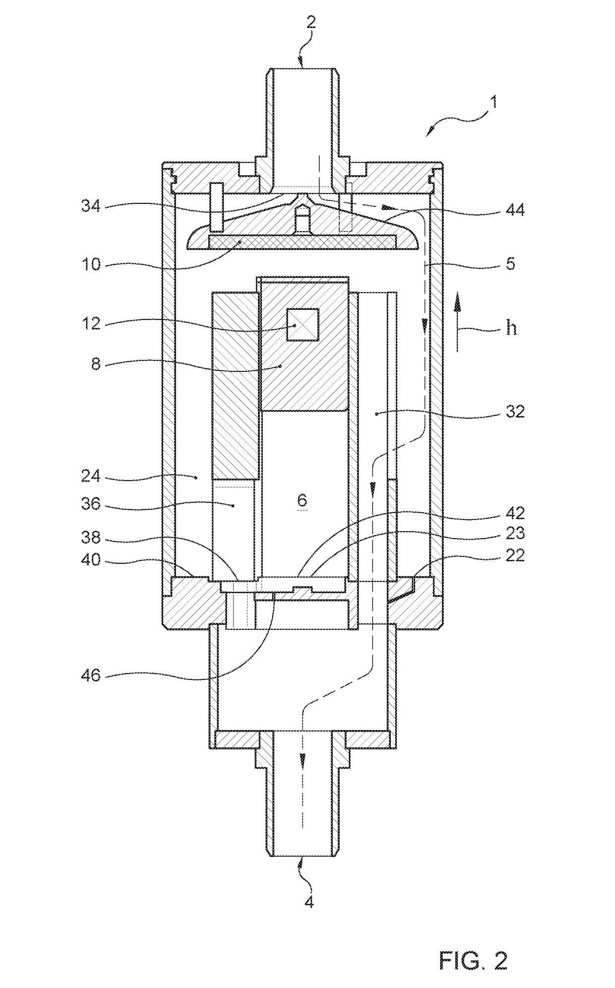
[0023]In FIG. 1, with reference numeral 1 a possible embodiment of a milk meter according to the invention is indicated. The milk meter is provided with an inlet 2 into which, in use, the milk flow whose flow rate is to be measured is supplied. Further, the milk meter is provided with an outlet 4 where the milk flow whose flow rate has been measured, in use, leaves the milk meter again. Between the inlet and the outlet extends a liquid flow path 5 which is schematically indicated in the drawing with a broken line. Obviously, the broken line concerns just one possible pathway along which the milk flow can proceed; reason why the representation is schematic.

[0024]The milk meter is provided with a measuring chamber 6 which is included in the liquid flow path 5. The milk meter is furthermore provided with a float 8 which is in the measuring chamber and which is configured to float on the milk of the milk flow that, in use, is in the measuring chamber. The milk meter is configured such t...


PUM


Abstract

Milk meter for measuring a flow rate of a milk flow, provided with an inlet, an outlet, and a liquid flow path from the inlet to the outlet. The milk meter has a measuring chamber and a float in the measuring chamber configured to float on milk. The milk meter determines the flow rate from the level of milk and the milk meter is provided with a magnetic unit for generating a magnetic field and the magnetic field varies in height direction of the measuring chamber, and the float has an electronic measuring unit for measuring the strength of the magnetic field. The measured strength of the magnetic field is a measure of the height at which the float is floating on the milk and the measured strength of the magnetic field is a measure of the flow rate of the milk flow.

Description

BACKGROUND OF THE INVENTION[0001]The invention relates to a milk meter for measuring a flow rate of a milk flow, provided with an inlet to which, in use, the milk flow is supplied, an outlet where the milk flow leaves the milk meter, in use, and a liquid flow path extending from the inlet to the outlet.[0002]Such milk meters, of diverse types, are known. Many known milk meters are mechanical fill and dump meters, which contain moving parts. A drawback of such mechanical milk meters is that the moving parts are subject to wear and require maintenance, and further are susceptible to pollution. The invention contemplates the provision of a milk meter that contains an improvement over known milk meters.CROSS-REFERENCE TO RELATED APPLICATIONS[0003]“Not Applicable”STATEMENT REGARDING FEDERALLY SPONSORED RESEARCH OR DEVELOPMENT[0004]“Not Applicable”THE NAMES OF THE PARTIES TO A JOINT RESEARCH AGREEMENT[0005]“Not Applicable”STATEMENT REGARDING PRIOR DISCLOSURES BY THE INVENTOR OR A JOINT IN...

Claims


Application Information

Patent Timeline
Patent Type & Authority Applications(United States)
IPC IPC(8): G01F1/52A01J5/01G01F1/00
CPCG01F1/52A01J5/01G01F1/007
Inventor VAN DIJK, JEROEN MARTIN
Owner N V NETHERLANDSCHE APPNFAB NEDAP
Why Eureka
Try Eureka