Centrifuge

a centrifuge and plate technology, applied in the field of centrifuges, can solve the problems of requiring much time and effort for the replacement of worn plates, requiring much time and effort for advance preparation, and requiring much time and effort for maintenance, so as to achieve the effect of reducing the burden on maintenance operations and simple replacemen

Pending Publication Date: 2022-03-24
TOMOE ENGINEERING CO LTD
View PDF0 Cites 0 Cited by
  • Summary
  • Abstract
  • Description
  • Claims
  • Application Information

AI Technical Summary

Benefits of technology

[0021]According to the present invention, solids discharged to a vicinity of the inner surface of the extension lug can be guided to the solid discharge port, while being slid along the wear-resistant sleeve. Thus, both solids flowing out to a position immediately below the solid discharge port and solids flowing out to a position other than the position immediately below the solid discharge port can be discharged from the solid discharge port (360° discharge). Thus, an increase in the diameter of the bowl is not necessary to increase the discharge amount of solids discharged. Additionally, the wear-resistant sleeve can be replaced simply by opening a casing of the centrifuge and unfastening the bolts. When the wear-resistant sleeve is replaced, the centrifuge need not be disassembled in the axial direction. Thus, a burden on a maintenance operation is alleviated.

Problems solved by technology

However, the centrifuge of Related Art 1 requires much time and effort when a worn plate is replaced.
Thus, the advance preparations require much time and effort.
Furthermore, a replacement operation for the plate requires scrape-off of an adhesive and re-bonding of a new plate to the extension lug.
Thus, maintenance requires much time and effort.
However, in a case where a treatment liquid includes a solid causing a high grinding force (for example, excavated earth), even a bushing member excellent in wear resistance is worn early, resulting in a shortened maintenance cycle.
Thus, a cumbersome maintenance operation including disassembling the centrifuge in an axial direction and replacing the bushing member needs to be performed in a short cycle.
Additionally, since an outer surface of the bushing member needs to be formed into a curved surface (see FIG. 3 of Patent Literature 3), the bushing member has an excessively large thickness, and processing costs for forming the curved surface is increased.

Method used


Image

  • Centrifuge
  • Centrifuge
  • Centrifuge

Examples


first embodiment

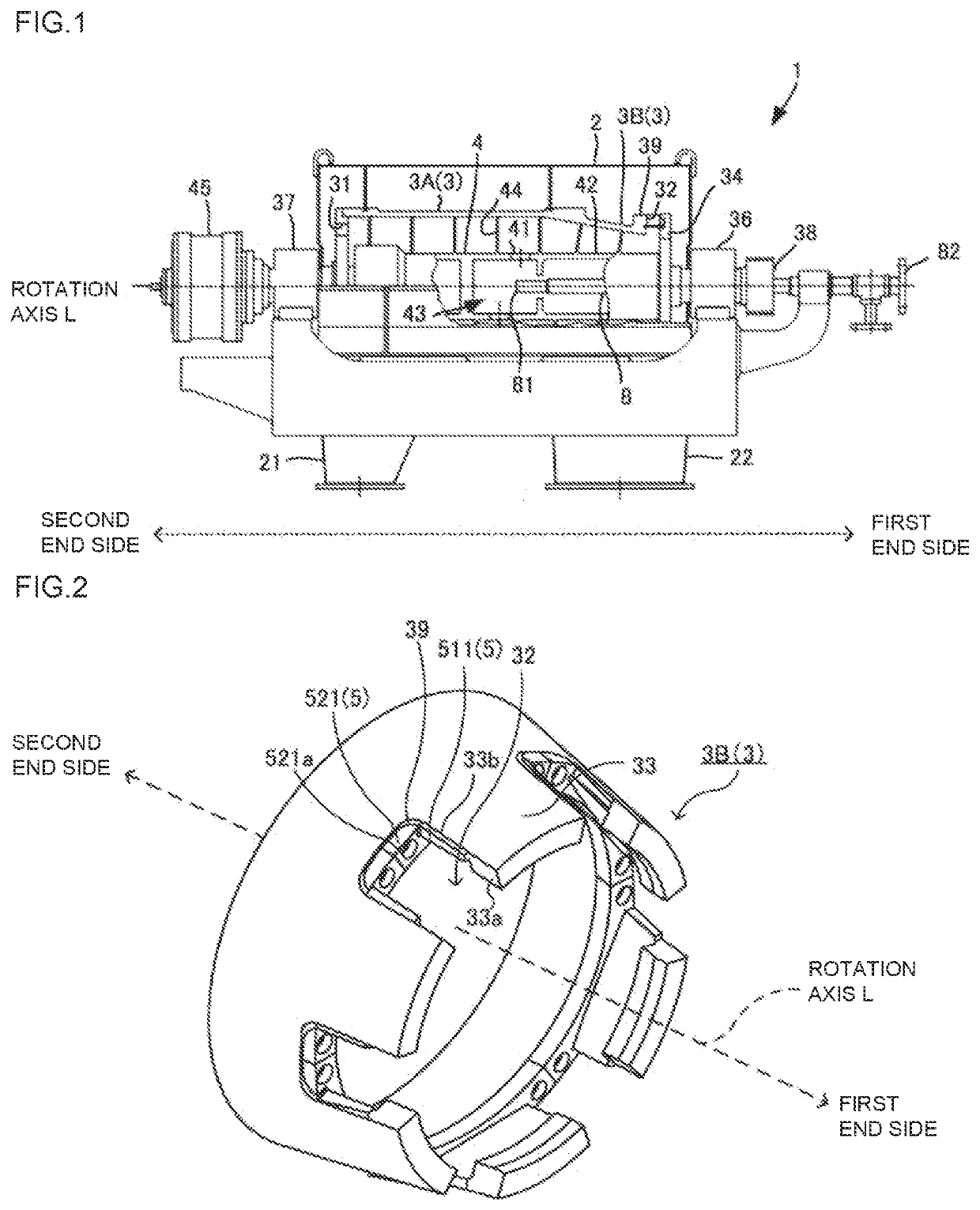
[0028]A centrifuge corresponding to a preferred embodiment of the present invention will be described below by taking a horizontal decanter 1 in FIG. 1 as an example. The decanter 1 includes wear-resistant sleeves having a configuration different from that of wear-resistant sleeves in the related art. In interpretation, the technical scope of the present invention is not limited by embodiments described below.

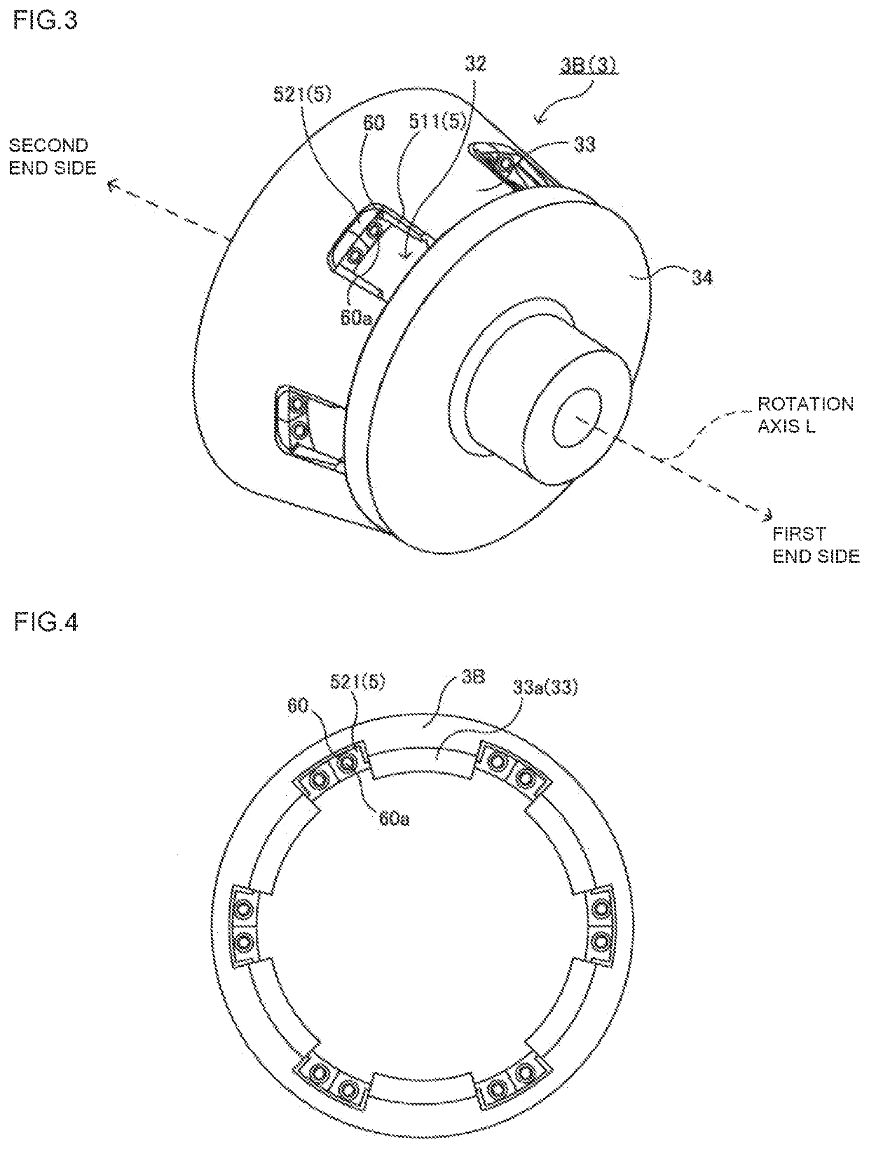
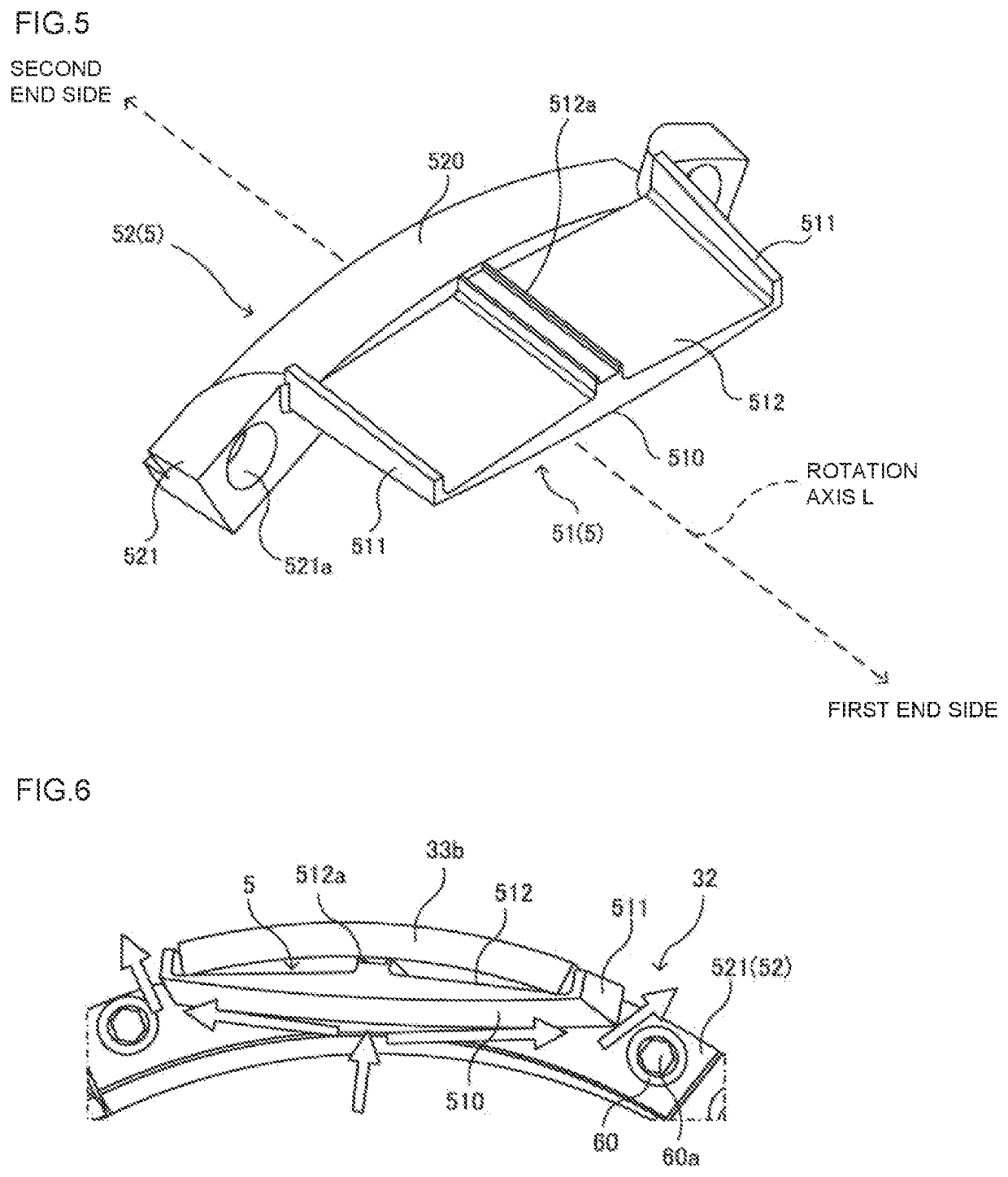
[0029]The decanter 1 includes a casing 2, a bowl 3, and a screw conveyor 4. The casing 2 houses the bowl 3 and the screw conveyor 4. The casing 2 is configured in an openable manner, and opening the casing 2 makes the bowl 3, solid discharge ports 32, wear-resistant sleeves 5, a hub 34, and the like visible as depicted in FIGS. 2 and 3 described below. The bowl 3 includes a bowl shell 3A and a bowl extension 3B. The bowl shell 3A is formed in a cylindrical shape having a constant inner diameter, and the bowl extension 3B is formed in a truncated conical shape. The bowl shell 3A...


PUM


Abstract

A centrifuge provided with: a bowl having a plurality of extension lugs formed on an opening rim section at one end of the bowl in the axial direction, the extension lugs being spaced apart from one another in the circumferential direction; a screw conveyer rotatably housed inside the bowl and rotatable at a different rotational speed than the bowl; a hub forming solid discharge ports between circumferentially adjacent pairs of the extension lugs, the hub connecting to the extension lugs and covering an opening of the opening rim section from the axial direction; and a wear-resistant sleeve including a sleeve body and a flange. The sleeve body covers lug inner surfaces of the extension lugs and the flange extends in an arced shape along the opening rim section. The sleeve body is attached with axially extending bolts to the opening rim section at a position that avoids the extension lugs.

Description

TECHNICAL FIELD[0001]The present invention relates to a centrifuge, and in particular to a wear-resistant sleeve installed at a solid discharge port of a bowl.BACKGROUND ART[0002]One of centrifuges that centrifuge a treatment object in a solid-liquid mixture state is known as a decanter (for example, see Patent Literature 1). FIG. 1 is a diagram depicting a configuration example of a horizontal decanter 1 and is a breakaway view depicting the inside of a casing 2 and the inside of a bowl 3. A configuration of the decanter 1 and problems with the decanter 1 will be described below in brief. A detailed configuration of the decanter 1 will be supplementally described below in embodiments.[0003]The decanter 1 includes a casing 2, a bowl 3 that has a tubular shape and that is housed in the casing 2, and a screw conveyor 4 housed in the bowl 3. The bowl 3 and the screw conveyor 4 rotate around a rotation axis L at different rotation speeds.[0004]A treatment object is fed into the screw co...

Claims


Application Information

Patent Timeline
Patent Type & Authority Applications(United States)
IPC IPC(8): B04B1/20B04B11/02
CPCB04B1/2008B04B2001/2091B04B11/02B04B1/20B04B7/12
Inventor NAGASU, MASARUTAHARA, YUHEI
Owner TOMOE ENGINEERING CO LTD
Why Eureka
Try Eureka