Bus bar assembly

a technology of bus bar and assembly, which is applied in the direction of connection contact member material, coupling device connection, conductor, etc., can solve the problems of insufficient reduction of net magnetic flux of apparatus, undesirable emf, and difficulty in arranging multiple capacitors, etc., to achieve the effect of improving figure legibility

Inactive Publication Date: 2009-07-21
CONTINENTAL AUTOMOTIVE SYST INC
View PDF7 Cites 16 Cited by
  • Summary
  • Abstract
  • Description
  • Claims
  • Application Information

AI Technical Summary

Problems solved by technology

An induced emf may be undesirable in an electric circuit as it may damage electrical circuit elements.
Simply due to their size, shape and physical design, it has heretofore been difficult to arrange multiple capacitors so as to reduce the magnetic flux in the manner described above.
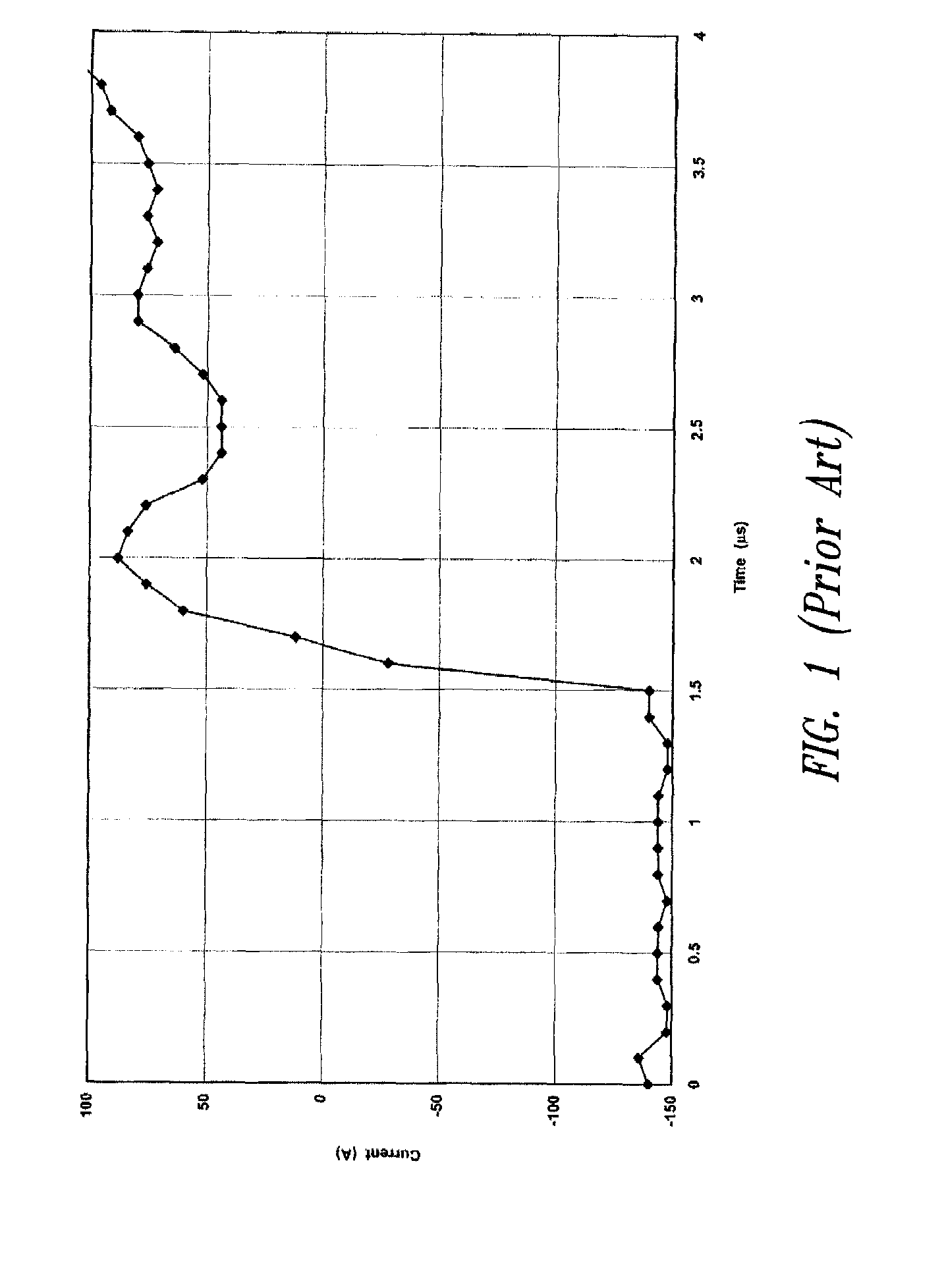
Capacitors are of particular concern because a discharging capacitor may produce a very high current that varies at an extremely rapid rate inducing a very large emf that may damage other elements in the circuit.
Apparatus in the art have attempted to arrange multiple capacitors with bus bar structures so as to reduce magnetic flux and induced emfs however, such apparatus do not reduce the net magnetic flux to a sufficient degree.
IGBTs unfortunately, are expensive and have high losses.

Method used


Image

  • Bus bar assembly
  • Bus bar assembly
  • Bus bar assembly

Examples


Embodiment Construction

[0033]In the following description, certain specific details are set forth in order to provide a thorough understanding of various embodiments. However, one skilled in the art will understand that the invention may be practiced without these details. In other instances, well-known structures have not been shown or described in detail to avoid unnecessarily obscuring descriptions of the embodiments.

[0034]Unless the context requires otherwise, throughout the specification and claims which follow, the word “comprise” and variations thereof, such as, “comprises” and “comprising” are to be construed in an open, inclusive sense, that is as “including, but not limited to.”

[0035]The headings provided herein are for convenience only and do not interpret the scope or meaning of the claimed invention.

[0036]Reference throughout this specification to “one embodiment” or “an embodiment” means that a particular feature, structure or characteristic described in connection with the embodiment is inc...


PUM


Abstract

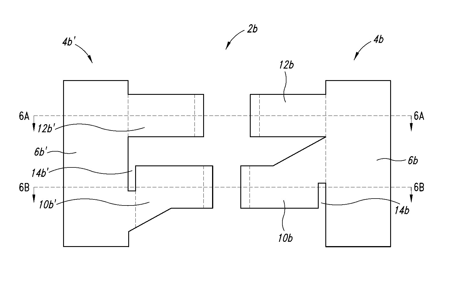
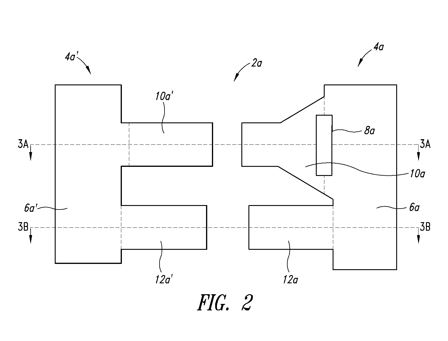
A bus bar assembly includes a first bus bar having at least first and second mounting arms and a second bus bar having at least third and fourth mounting arms. The first and third mounting arms are adapted to alternately interleave with one another such that the position of the first mounting arm relative to the third mounting arm is opposite as to the position of the second mounting arm relative to the fourth mounting arm.

Description

BACKGROUND OF THE INVENTION[0001]1. Field of the Invention[0002]The present disclosure relates to bus bar assemblies.[0003]2. Description of the Related Art[0004]Bus bars are structures that electrically couple electrical elements, such as capacitors and solid state devices, in an electric circuit.[0005]As is well known in the art, any electric current may have an associated magnetic field. The magnitude of the associated magnetic field is proportional to the magnitude of the current. In a uniform material, the magnitude of the magnetic field is also proportional to the inverse of the square of the distance from the current. The direction of the magnetic field is perpendicular to the direction of current.[0006]Where the current changes as a function of time, the associated magnetic field may also change as a function of time. A changing magnetic field may in turn produce a changing magnetic flux. A changing magnetic flux may induce an emf in a circuit. The magnitude of the induced e...

Claims


Application Information

Patent Timeline
Patent Type & Authority Patents(United States)
IPC IPC(8): H02G5/00
CPCH02G5/02
Inventor KIMMEL, JOSEPH S.
Owner CONTINENTAL AUTOMOTIVE SYST INC
Why Eureka
Try Eureka