Side-emitting LED package with improved heat dissipation

a technology of led package and heat dissipation, which is applied in the direction of basic electric elements, electrical appliances, lighting and heating apparatus, etc., can solve the problems of premature total device failure, shorten the life, reduce the light conversion efficiency, etc., and achieve the effect of less thermal resistan

Active Publication Date: 2009-07-28
AVAGO TECH INT SALES PTE LTD
View PDF6 Cites 78 Cited by
  • Summary
  • Abstract
  • Description
  • Claims
  • Application Information

AI Technical Summary

Problems solved by technology

In addition to reducing the light conversion efficiency, heat also shortens the lifetime of the LED and can lead to premature total device failure.
In many applications, the color shift is more objectionable than the decrease in intensity of the light source.
The rate at which LEDs age depends on the operating temperature of the LEDs, higher operating temperatures leading to more rapid aging.
However, lead frame packages that provide sufficient heat dissipation are not available for high power dies.
These packages typically rely on moving heat from the LED to an outside heat-dissipating surface since the surface area of the LED package is too small to dissipate heat to the air surrounding the LED.
Unfortunately, the lead heat path tends to have too high of a thermal resistance, and hence, the die must run at a substantially elevated temperature to force the heat through the lead.

Method used


Image

  • Side-emitting LED package with improved heat dissipation
  • Side-emitting LED package with improved heat dissipation
  • Side-emitting LED package with improved heat dissipation

Examples


Embodiment Construction

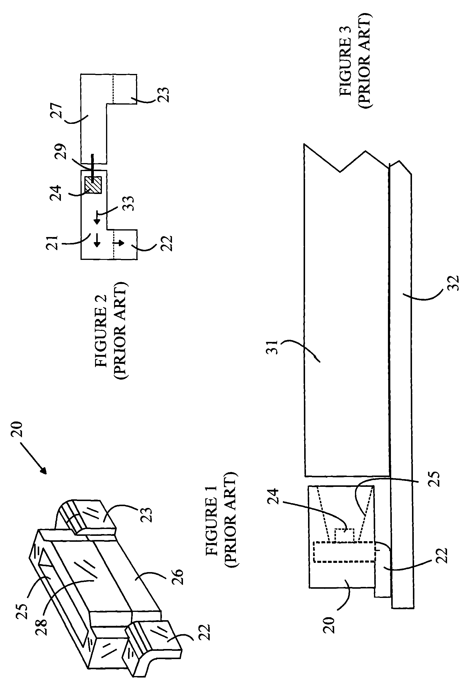
[0017]The manner in which the present invention provides its advantages can be more easily understood with reference to FIGS. 1-3, which illustrate a prior art side-emitting packaged LED light source. FIG. 1 is a perspective view of light source 20 and FIG. 2 is a top view of the lead frame used in light source 20. FIG. 3 is a cross-sectional view of light source 20 mounted to provide illumination of a light pipe. Light source 20 includes an LED 24 that is mounted on lead 21 of the lead frame shown in FIG. 2. LED 24 includes first and second contacts that are used to power LED 24. The first contact is on the bottom surface of LED 24 and is connected electrically to lead 21. The second contact is on the top surface of LED 24 and is connected to lead 27 by a wire bond 29. LED 24 is bonded to lead 21 by an adhesive that is both thermally and electrically conductive, so that the heat generated in LED 24 is transferred to lead 21.

[0018]The lead frame is encapsulated in a body 26 from whi...


PUM


Abstract

A light source and a method for making the same are disclosed. The light source includes a lead frame, an integrated circuit chip and a body. The lead frame has first and second sections. The first section includes a lateral portion, a chip mounting area and a first extension. The integrated circuit chip is bonded to the first section in the chip mounting area and is in thermal contact with the chip mounting area. The body has top, bottom, and side surfaces. The first extension is bent to provide a heat path from the chip mounting area to the side surface, a surface of the first extension that is not in contact with the side surface forming a first planar bonding surface. The heat path has less thermal resistance than a heat path through the lateral portion.

Description

BACKGROUND OF THE INVENTION[0001]Light-emitting diodes (LEDs) are attractive candidates for replacing conventional light sources such as incandescent bulbs and fluorescent tubes. LEDs have significantly greater energy conversion efficiencies than incandescent bulbs and, in some cases, higher energy conversion efficiencies than fluorescent tubes. Furthermore, the conversion efficiencies of LEDs are steadily improving over time, and hence, LEDs will provide significant energy savings in the not too distant future.[0002]In addition, LEDs have lifetimes that are much greater than the lifetime of either fluorescent lights or incandescent bulbs. This advantage is particularly important in applications in which the cost of changing a bulb or fluorescent tube is high. Automobile taillights and traffic signal lights are already being converted to LED-based lighting systems to take advantage of this aspect of LEDs.[0003]Finally, LEDs are “point sources”, and hence, are better suited than fluo...

Claims


Application Information

Patent Timeline
Patent Type & Authority Patents(United States)
IPC IPC(8): F21V7/04H01L33/48H01L33/62H01L33/64
CPCH01L33/62H01L33/647H01L33/486H01L33/642H01L2224/48091H01L2224/48247H01L2224/73265H01L2224/32245H01L2924/00014H01L2924/00
Inventor OON, SIANG LINGMOK, THYE LINNLOON, KHA YAN
Owner AVAGO TECH INT SALES PTE LTD
Why Eureka
Try Eureka