System and method for advanced power management

a power management and advanced technology, applied in the field of management of power supply systems, can solve problems such as millions of dollars in losses, expensive and time-consuming, and public hazards

Active Publication Date: 2009-07-28
NAT TECH & ENG SOLUTIONS OF SANDIA LLC
View PDF9 Cites 37 Cited by
  • Summary
  • Abstract
  • Description
  • Claims
  • Application Information

AI Technical Summary

Problems solved by technology

These examples include events resulting in millions of dollars of losses, and events creating public hazards (including air traffic control system failures).
Standby power systems are put into use only rarely, as utility outages are themselves rare.
Because accurate testing of the standby power supplies is generally performed manually at d

Method used


Image

  • System and method for advanced power management
  • System and method for advanced power management
  • System and method for advanced power management

Examples


Embodiment Construction

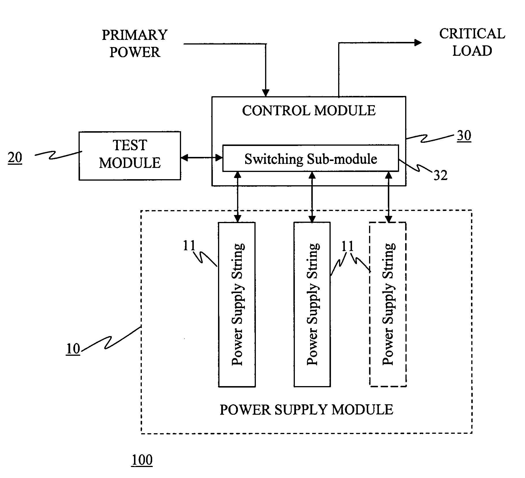
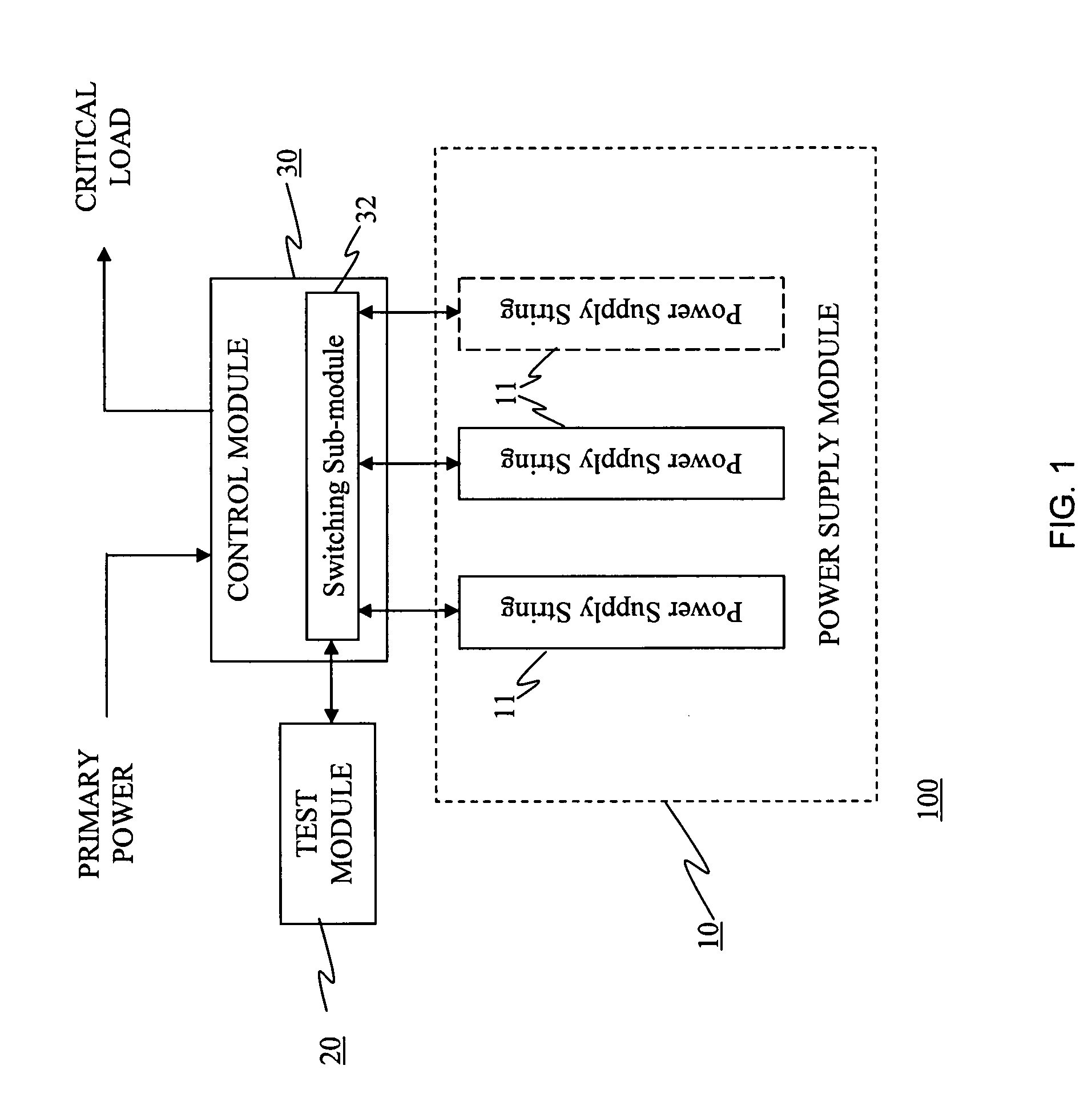
[0009]The present invention can be implemented in simple, inexpensive, and robust systems and methods to assure assuring that power sources will operate as expected when necessary to supply critical loads in the event of a power failure.

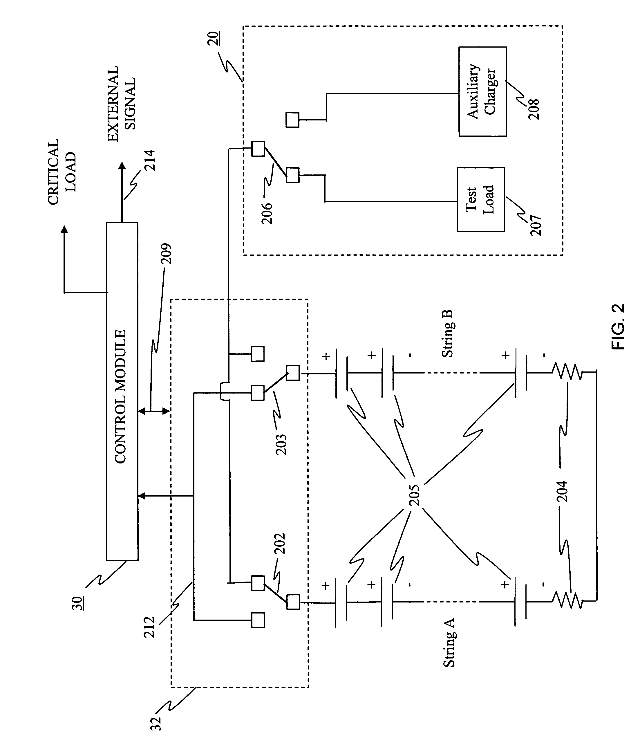
[0010]In a power management system 100 according to the present invention, plural strings of power supplies 11, such as batteries, comprise a power supply module, or power supply means, 10 that is operably connected to a control module, or control means, 30, as illustrated in FIG. 1. The control module comprises both hardware and software and is operatively arranged to switch through a switching sub-module 32 one of the plural power supply strings into a test mode in conjunction with the testing module 20, while keeping the remainder of the plural power supply strings in ready-to-be-used mode so that standby power can be transmitted to critical loads as required in the event of a failure of the primary power supply. At least two power supply strings ...


PUM


Abstract

A power management system is provided that includes a power supply means comprising a plurality of power supply strings, a testing means operably connected to said plurality of power supply strings for evaluating performance characteristics of said plurality of power supply strings, and a control means for monitoring power requirements and comprising a switching means for controlling switching of said plurality of power supply strings to said testing means.

Description

STATEMENT OF GOVERNMENT INTEREST [0001]The United States Government has rights in this invention pursuant to Department of Energy Contract No. DE-AC04-94AL85000 with Sandia Corporation.BACKGROUND OF THE INVENTION [0002]The present invention is related to managing power supply systems and, more particularly, to a standby power supply system that ensures continuously-available standby power.[0003]Many industries and applications have a critical need to assure that power sources will be able to supply critical loads in the event of a power failure. Such industries include, but are not limited to, telecommunications, power utilities, information technologies (for example, in banking, stock brokerage, and insurance applications) industries, and critical care medical facilities. Countless examples exist of power sources failing to operate as needed when required. These examples include events resulting in millions of dollars of losses, and events creating public hazards (including air tra...

Claims


Application Information

Patent Timeline
IPC IPC(8): H02J7/00
CPCG01R31/40H02S50/00H02S50/10Y02E10/50
Inventor ATCITTY, STANLEYSYMONS, PHILIP C.BUTLER, PAUL C.COREY, GARTH P.
Owner NAT TECH & ENG SOLUTIONS OF SANDIA LLC
Why Eureka
Try Eureka