
Image alignment system with overlying frame in display

a technology of image alignment and display, which is applied in the field of imaging systems, can solve the problems of affecting the operation of the portable imaging device, the user's difficulty in aligning the device in a horizontal or vertical direction, and the inability to achieve proper horizontal or vertical alignment, etc., and achieves the effect of simple and flexible procedure, efficient and flexible procedure, and simple and flexible procedur

Active Publication Date: 2009-07-28
SONY CORP
View PDF13 Cites 15 Cited by
  • Summary
  • Abstract
  • Description
  • Claims
  • Application Information

AI Technical Summary

Benefits of technology

[0009]The present invention is directed to providing a user of a portable device with an efficient and flexible procedure for aligning an image. In particular, the present invention is directed to providing a simple, flexible, and intuitive aligning technique. One implementation of the present invention may provide a portable device with an efficient and flexible procedure for aligning an image. In particular, an implementation of the present invention may provide a simple, flexible, and intuitive aligning procedure.

Problems solved by technology

Many circumstances exist in which a user of a portable imaging device is presented with difficulties in aligning the device in a horizontal or vertical direction while operating the device.
Difficulties in aligning the device may also occur when the user holds the device with arm extended at a distance from the head and body of the user.
Apart from these situations, difficulties in achieving a proper horizontal or vertical alignment may occur in cases in which the object to be captured has no readily apparent horizontal or vertical reference.
A misaligned orientation of an image-capturing device may result in a tilted image with reference to a display orientation of the captured image.
Image stabilization systems such as those mentioned above, however, are limited to “sharpening” an image by counteracting camera movement experienced during operation of the camera.
Although such systems may counteract effects of movement of the camera during image capture, such systems are less effective at counteracting or correcting an angle at which the camera is operated relative to an object in a captured image.
It follows that image stabilization technologies are not intended to resolve misalignment effects when it comes to aligning the camera horizontally or vertically.

Method used


Image

  • Image alignment system with overlying frame in display
  • Image alignment system with overlying frame in display
  • Image alignment system with overlying frame in display

Examples


Embodiment Construction

[0039]The present invention relates to portable devices and an associated imaging system. In particular, the invention relates to portable communication devices that include an imaging system. However, the invention is not limited to communication devices. Rather, it can be applied to any suitable portable device comprising a suitable imaging system.

[0040]The terms “image” or “images” are intended to comprise still images, a series or sequence of images, as well as moving images, unless otherwise is explicitly stated or is clear from the context.

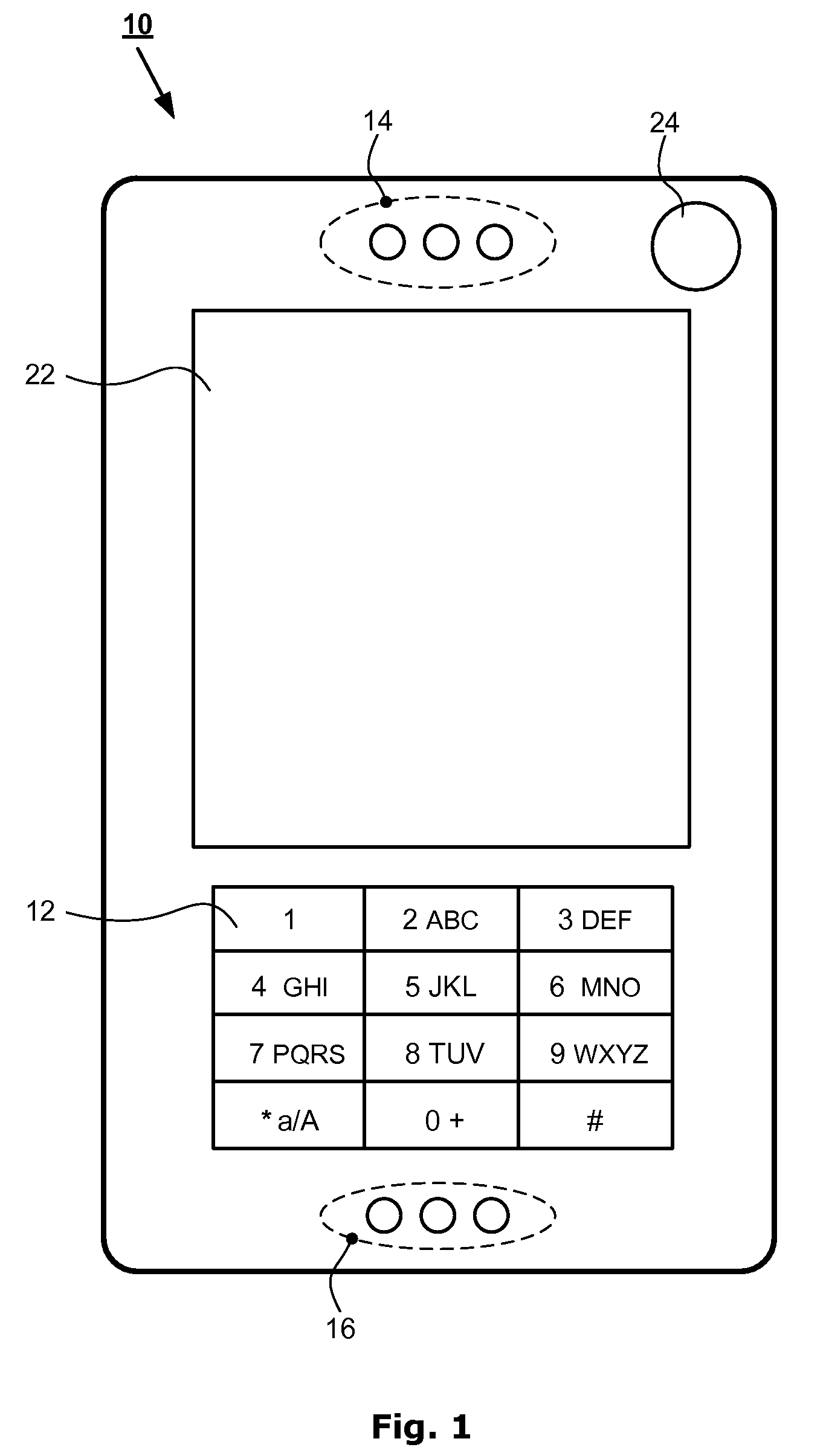
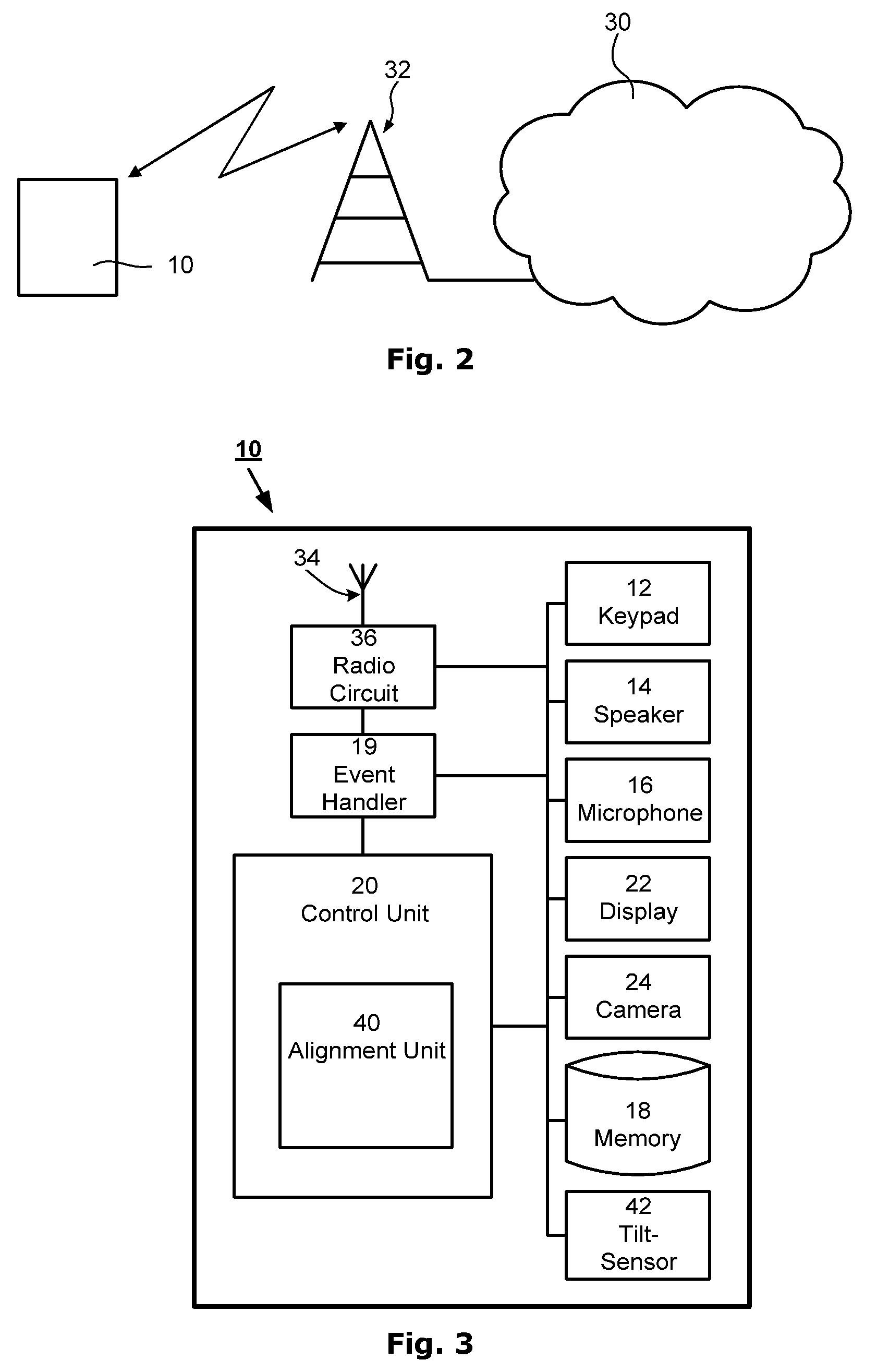
[0041]A portable communication device according to one embodiment of the present invention is shown in FIG. 1. The device may include a phone 10, such as a mobile cell phone, adapted, for example to operate according to 3G-technology (e.g. W-CDMA or CDMA2000) or possibly according to 2,5-technology (e.g., GPRS) or other communication technology. Information about 3G-technology, 2,5-technology, etc., can be found in specifications from the 3r...


PUM


Abstract

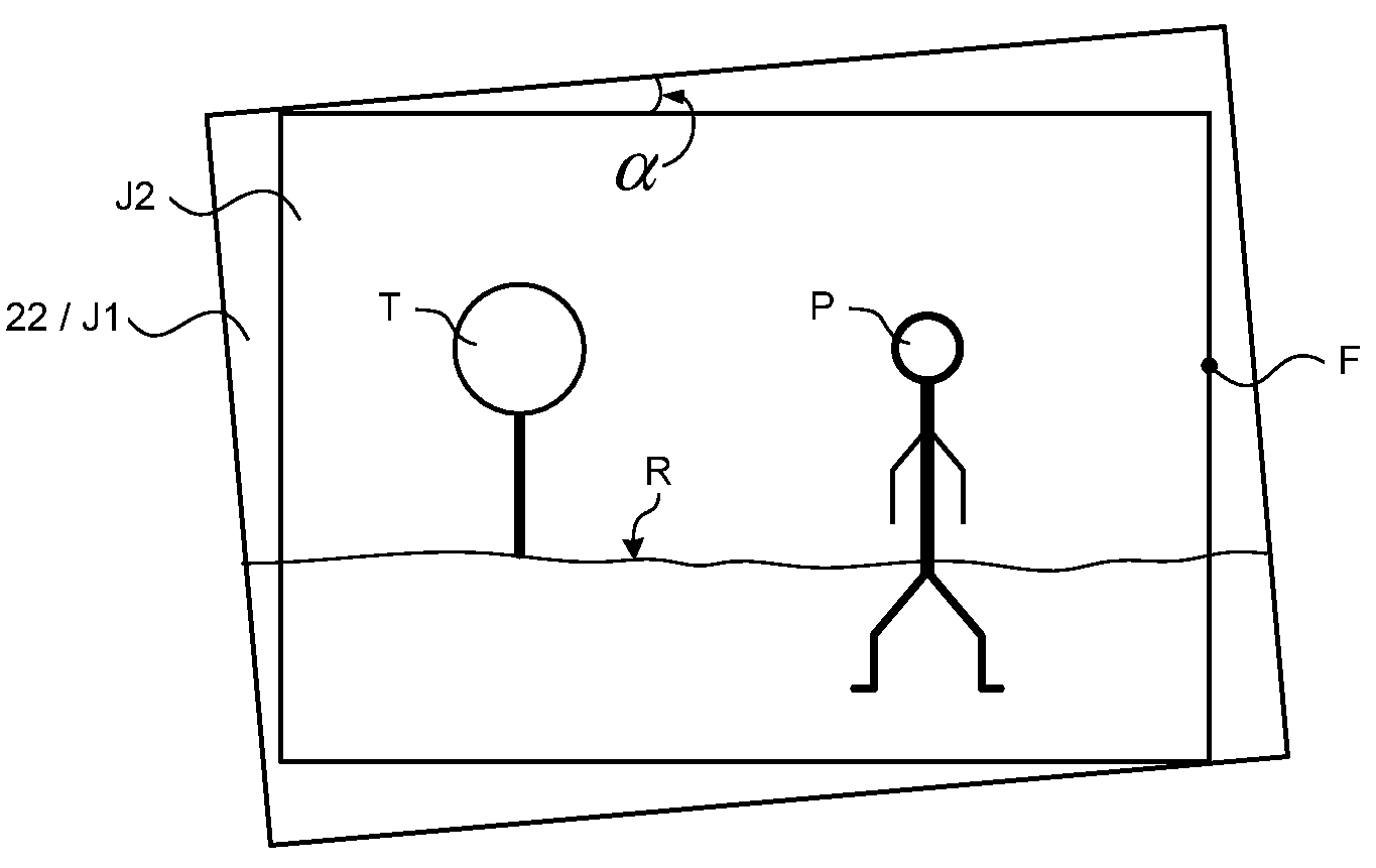
In an imaging device including an image recording arrangement, a tilt-sensor, and a display, a method may include detecting a tilt-angle for the image recording arrangement using the tilt-sensor; and presenting at least one marker-arrangement via the display indicative of the tilt-angle.

Description

RELATED APPLICATIONS[0001]This application claims priority under 35 U.S.C. §119 based on U.S. Provisional Application Ser. No. 60 / 867,155, filed Nov. 24, 2006, the disclosure of which is incorporated herein by reference.BACKGROUND[0002]1. Technical Field of the Invention[0003]The present invention relates to devices having an imaging system and, more particularly, a method and an arrangement for aligning an image in an imaging device.[0004]2. Description of Related Art[0005]Many circumstances exist in which a user of a portable imaging device is presented with difficulties in aligning the device in a horizontal or vertical direction while operating the device. Typical examples include situations in which the user, the device, and / or the object to be recorded are moving relative to each other, e.g., use of the device from a moving vehicle, an unsteady hand of the user for whatever reason, following the object to be recorded afoot, etc. Difficulties in aligning the device may also occ...

Claims


Application Information

Patent Timeline
Patent Type & Authority Patents(United States)
IPC IPC(8): G03B17/00G03B17/18H04N5/228
CPCG03B17/20G06F1/1626G06F1/1684G06F1/1686H04N5/23293G06T3/60H04N5/23241G06F3/0346G06F2200/1614G06F2200/1637H04N23/635
Inventor KLINGHULT, GUNNARKLEVERMAN, MATS
Owner SONY CORP
Learn More