
Selecting autofocus area in an image

a technology of autofocus and image, applied in the field of image selection, can solve the problems of inability to focus the image on an object in the typical focus frame, and the inability to know whether the desired object will be in focus, and achieve the effect of efficient and flexible procedur

Active Publication Date: 2008-04-03
SONY CORP
View PDF11 Cites 70 Cited by
  • Summary
  • Abstract
  • Description
  • Claims
  • Application Information

AI Technical Summary

Benefits of technology

[0007]Implementations consistent with the principles of the present invention are directed to providing a user of a portable imaging device with an efficient and flexible procedure for focusing an image at a desired area of interest. In particular, some implementations are intended to provide a simple, flexible, and intuitive focusing procedure which requires few or no additional actions by the user.
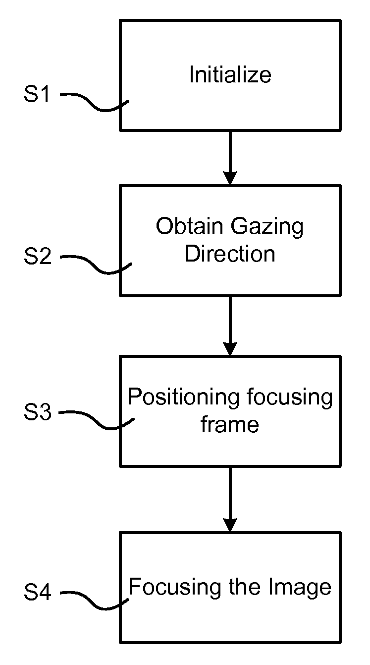
[0027]In a further implementation, a computer-readable medium may contain instructions for execution on a processor, the instructions to cause: a first image recording arrangement to record images of an user of a device; a second image recording arrangement, including an autofocus arrangement, to record images of viewable surroundings; and a display arrangement for reproducing the recorded images of the viewable surroundings; and an autofocus-control to: obtain a gazing direction of the user based on the images of the user; identify an area of interest in the image rendered via the display based on the obtained gazing direction; focus the recorded image of the viewable surroundings using the autofocus arrangement so that visual acuity associated with an object within the identified area of interest is increased.

Problems solved by technology

However, since an entire (multi-depth) viewable image may not be focused on at the same time, a need exists for determining the portion of the viewed image that the user wishes to focused on in the captured image.
If the focus frame is aimed otherwise, it is uncertain that the desired object will be in focus in the captured image.
Given that the focus frame is typically centered in the viewfinder, however, typical focus frames do not allow the focus of the image on an object that is located outside the image center, i.e. located in the periphery of the image.

Method used


Image

  • Selecting autofocus area in an image
  • Selecting autofocus area in an image
  • Selecting autofocus area in an image

Examples


Embodiment Construction

[0041]Implementations of the present invention relate to devices having an imaging or image capturing system. In particular, the invention relates to portable communication devices comprising an imaging system. However, the invention is by no means limited to communication devices. Rather, it can be implemented in any suitable portable device having a suitable imaging system.

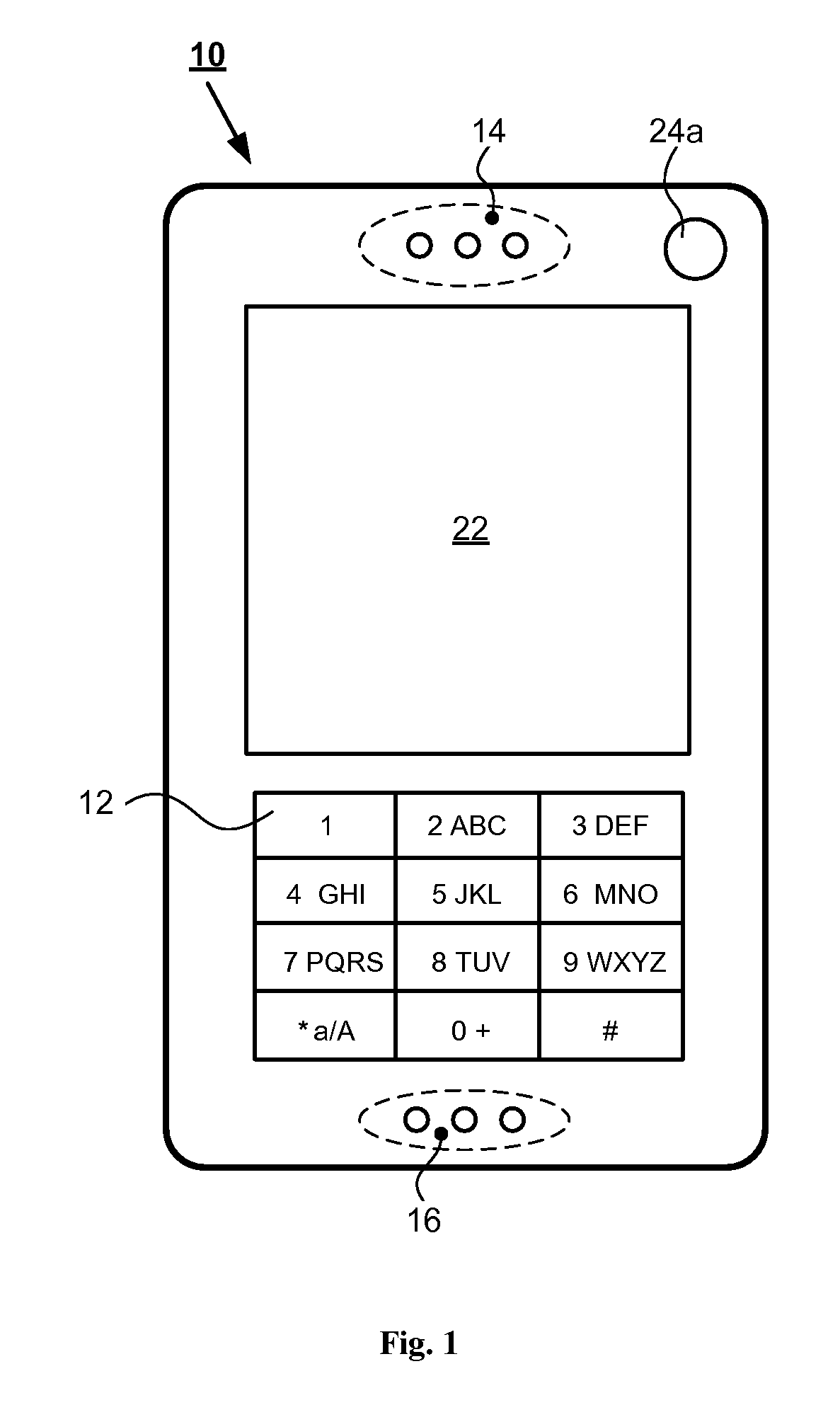
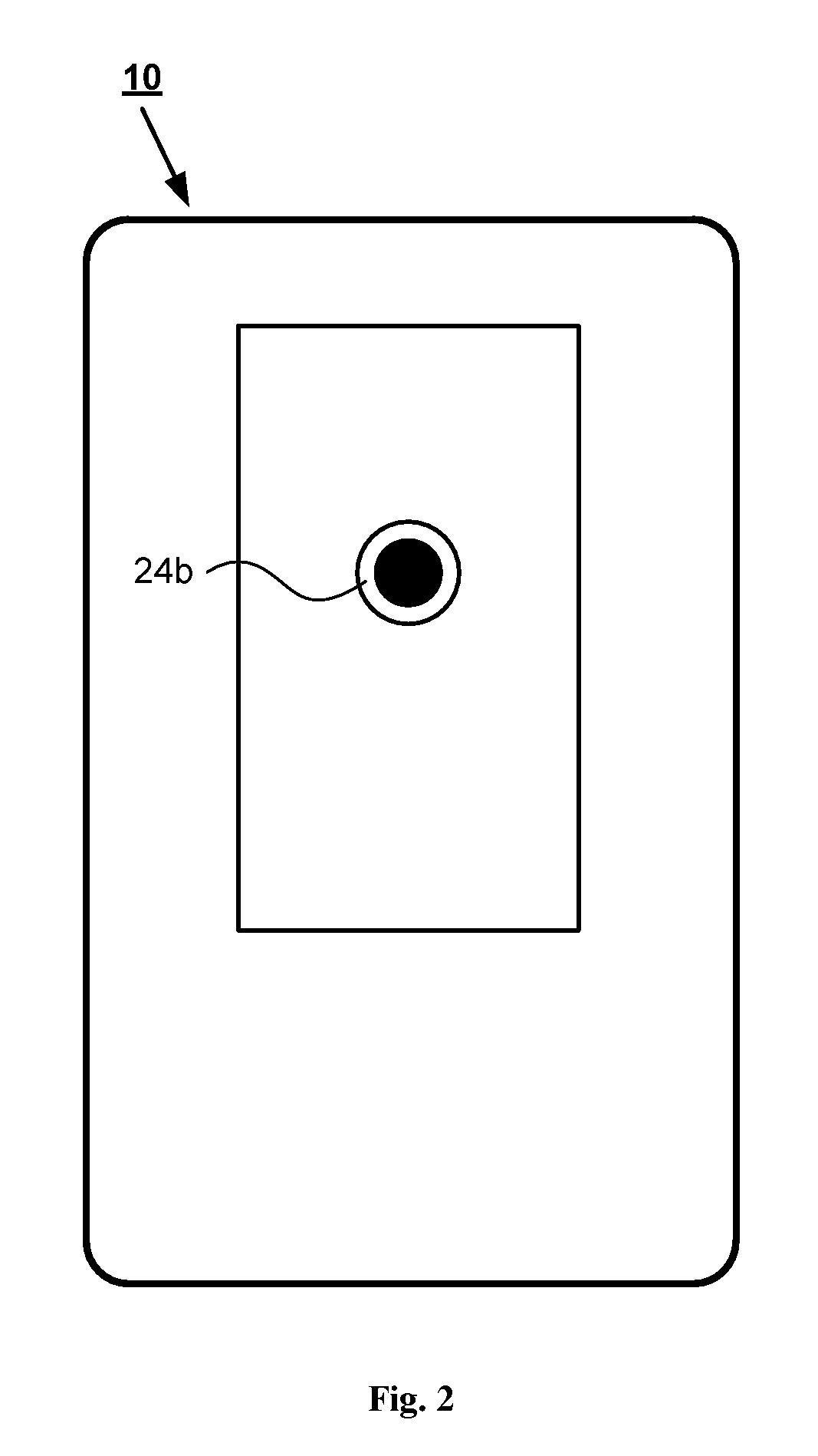
[0042]A portable communication device according to a preferred embodiment of the invention is shown in FIG. 1-2. The device is preferably a mobile cell phone 10 adapted, for example, to operate according to 3G-technology (e.g., W-CDMA or CDMA2000), 2.5-technology (e.g., GPRS), or other type of technology. Information about 3G-technology and 2.5-technology can be found in specifications from the 3rd Generation Partnership Project (3GPP) (see, e.g., www.3gpp.org).

[0043]FIG. 1 shows a first side of cell phone 10 that may include a keypad 12, a speaker 14, and / or a microphone 16. Keypad 12 may be used for entering i...


PUM


Abstract

A system and method are provided for obtaining a gazing direction of a user of an image-capturing device relative to an image of an object to be captured; identifying an area of the image based on the obtained gazing direction; and performing optical focusing for the identified area using an autofocus arrangement of the image-capturing device.

Description

TECHNICAL FIELD OF THE INVENTION[0001]The present invention generally relates to imaging systems and, more particularly, portable communication devices having an imaging system and a method and an arrangement for selecting the focus area in an image in an imaging system.DESCRIPTION OF RELATED ART[0002]In portable imaging devices, the correct focus of an image can be obtained by means of a so-called autofocus arrangement. For most Digital Still Camera (DSC) purposes, autofocusing arrangements may be considered superior to a manual adjustment of the image focus in terms of speed and accuracy.[0003]Autofocus arrangements are typically based on either an active system or a passive system. The active systems usually involves two steps. Initially, a distance measuring (e.g., based on ultrasonic sound waves, infrared light, or the like) is performed apart from the optical system. Subsequently, a focus adjustment is performed by the optical system based on the measured distance. In contrast...

Claims


Application Information

Patent Timeline
Patent Type & Authority Applications(United States)
IPC IPC(8): G03B13/34
CPCG02B7/287G02B27/0093H04M1/0264H04N5/23212H04N5/23293G03B13/36H04N23/675H04N23/635G06F3/013
Inventor GRIP, MARTIN
Owner SONY CORP
Learn More