Scissor suspension

a scissor and roller technology, applied in the field of scissor suspension, can solve the problems of reducing the effectiveness of the operator and the time, affecting the operation efficiency of the operator, and the roller only having one point of contact,

Inactive Publication Date: 2009-08-04
CATERPILLAR INC
View PDF17 Cites 49 Cited by
  • Summary
  • Abstract
  • Description
  • Claims
  • Application Information

AI Technical Summary

Benefits of technology

[0012]A method is also provided for using an example of a scissor suspension. The scissor suspension may include a first arm having a first end pivotally attached to a structure and a second end. The scissor suspension may also include a first bearing pivotally connected proximate to the second end of the first arm and a second arm having a first end and a second end that may be pivotally connected to the first arm between the first and second ends of the first and second arms. The first bearing may be moveably coupled to the first rail and the scissor suspension may also include a damper disposed to dampen movement of the first rail relative to the structure.

Problems solved by technology

However, these machines often vibrate during operation, which may cause the operator may fatigue quickly reducing the effectiveness of the operator and the time the operator is able to actively operate the machine.
However, a roller may only have one point of contact while moving in a track.
Thus, roller-type scissor suspensions suffer from excessive wear and premature failure.
The inherent looseness of roller-type scissor suspensions may prevent the scissor suspension from adequately reducing the vibrations transmitted from the machine to the seat.
Additionally, roller-type scissor suspensions are susceptible to dirt and debris building up in the tracks that inhibit proper movement of the rollers and promote wear and premature failure of the roller-type scissor suspension.
However, linkage-type scissor suspensions may suffer from excessive friction and stiffness, which may prevent linkage-type scissor suspensions from properly moving to dampen the vibrations and shocks of machine use and travel.
Additionally, linkage-type scissor suspensions do not support integrated fore-aft or lateral motion dampening.
In recent years, more and more equipment has been connected and attached to the seat, significantly increasing the weight that a scissor suspension is required to support.
However, these roller-type and linkage-type scissor suspensions may not be robust enough to support this additional weight and effectively dampen the vibrations of the machine.
Additionally, when these roller-type and linkage-type scissor suspensions are used, they suffer from accelerated wear and premature failure resulting from this increased weight.

Method used


Image

  • Scissor suspension
  • Scissor suspension
  • Scissor suspension

Examples


Embodiment Construction

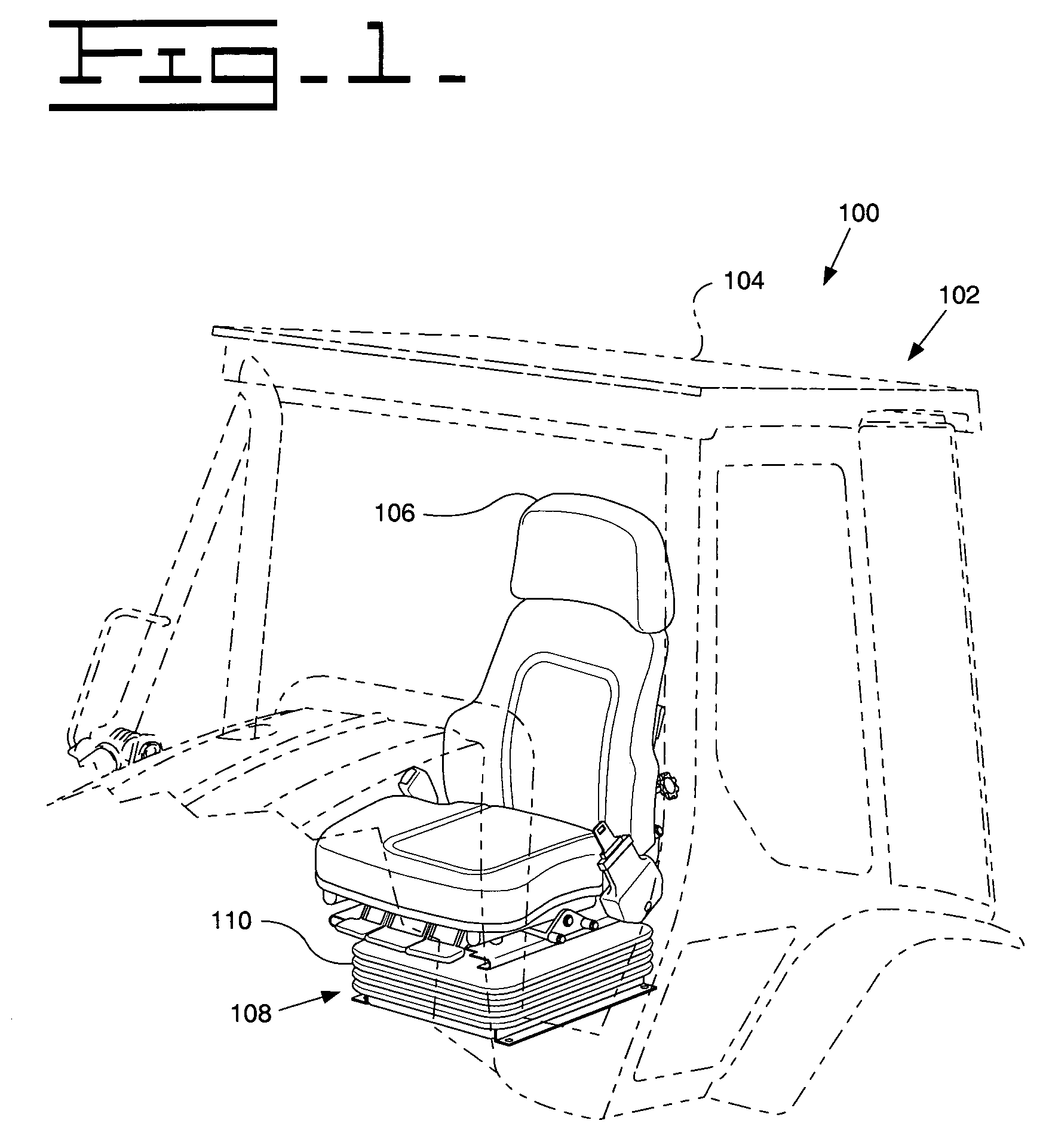
[0021]Referring to FIG. 1, a perspective view illustrates a structure 100, which may be a machine 102 that includes an operator compartment 104. The machine 102 may be a backhoe loader, agricultural tractor, track-type tractor, articulated truck, wheel loader, and other types of construction, mining, or agricultural machinery.

[0022]As shown, the operator compartment 104 may include a seat 106 mounted on a suspension system 108. The suspension system 108 is attached to the structure 100 and dampens the vibrations associated with the operation of the machine 102 in order to increase operator comfort while seated in the seat 106.

[0023]The suspension system 108 may include a shroud 110 that conforms to the movement of the suspension system 108. The shroud 110 helps prevents contaminates such as water, dirt, rocks and other objects from affecting the performance of the suspension system 108. The shroud 110 may be made of cloth, an elastomer or other plastic, and any other material known ...


PUM


Abstract

A scissor suspension includes a first arm having a first end and a second end. The first end may be configured for pivotal attachment to a structure and a first bearing may be pivotally connected proximate to the second end of the first arm. A second arm having a first end and a second end may be pivotally connected to the first arm between the first and second ends of the first and second arms. The first bearing may be moveably coupled to the first rail.

Description

TECHNICAL FIELD[0001]This invention relates generally to a scissor suspension for reducing vibrations transmitted through the scissor suspension.BACKGROUND[0002]Machines, such as skid steer loaders, multi-terrain loaders, backhoe loaders, agricultural tractors, track-type tractors, articulated trucks, wheel loaders, off-road vehicles, dump trucks, and other types of construction, mining, and agricultural machinery are used for a variety of tasks requiring operator control. Typically, an operator controls these machines while seated in a seat located on the machine for extended periods of time. However, these machines often vibrate during operation, which may cause the operator may fatigue quickly reducing the effectiveness of the operator and the time the operator is able to actively operate the machine.[0003]Consequently, suspensions have been developed to reduce the vibrations passed from the operating machine to the seat of the operator. For example, U.S. Pat. No. 5,251,864 illus...

Claims


Application Information

Patent Timeline
Patent Type & Authority Patents(United States)
IPC IPC(8): F16M1/00B60N2/02
CPCB60N2/502B60N2/509B60N2/544B60N2/508
Inventor CATTON, JONATHAN C.
Owner CATERPILLAR INC
Why Eureka
Try Eureka