Display device and display method

a technology of a display device and a display method, which is applied in the direction of instruments, digital computers, cathode-ray tube indicators, etc., can solve the problems of high cost or space requirements, and achieve the effect of easy obtaining a video signal and high quality

Active Publication Date: 2009-08-04
FUJITSU GENERAL LTD
View PDF64 Cites 8 Cited by
  • Summary
  • Abstract
  • Description
  • Claims
  • Application Information

AI Technical Summary

Benefits of technology

[0007]Under these circumstances, the invention has been made. The invention provides a display device, which can easily obtain a video signal with high quality without executing a complicated process with respect to a video source signal.

Problems solved by technology

In this example, if two display devices are required to satisfy the both needs, a problem such as high cost or a need for space arises.

Method used


Image

  • Display device and display method
  • Display device and display method
  • Display device and display method

Examples


Embodiment Construction

[0064]Hereinafter, display devices according to embodiments of the invention will be described with reference to the accompanying drawings. It is to be understood that scope of the invention is not limited to the following embodiments but covers inventions as set forth in claims and their equivalents.

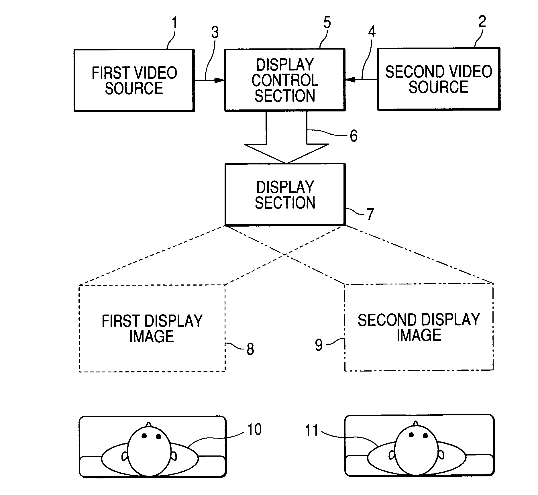
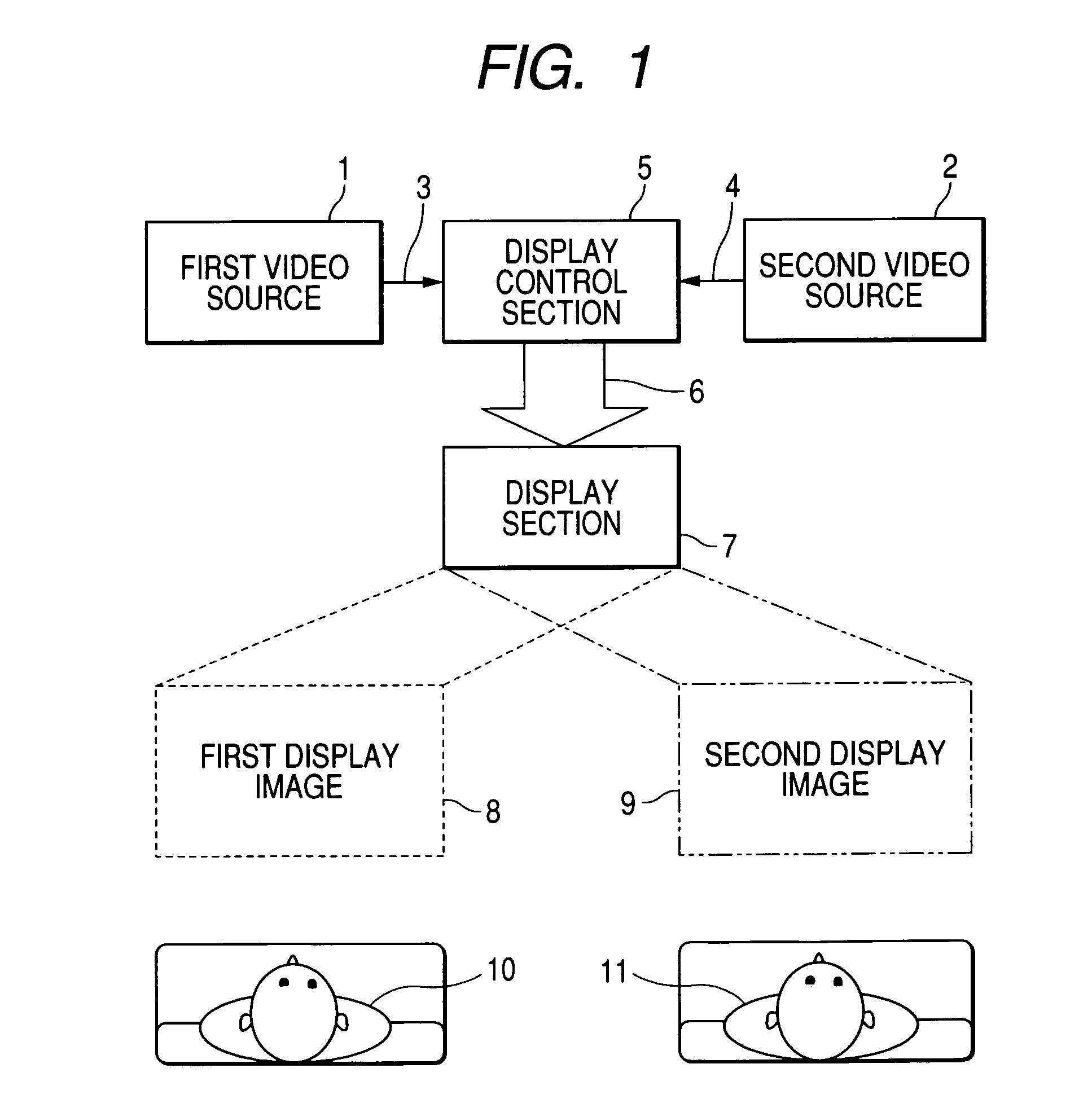
[0065]FIG. 1 is a conceptual diagram of a multi-view display device (hereinafter, abbreviated as “display device”) according to one embodiment of the invention. In the figure, reference numeral 1 denotes a first video source, reference numeral 2 denotes a second video source, reference numeral 3 denotes first video data from the first video source 1, reference numeral 4 denotes second video data from the second video source 2, reference numeral 5 denotes a display control section, reference numeral 6 denotes display data, reference numeral 7 denotes a display section (for example, a liquid crystal panel or the like), reference numeral 8 denotes a first display image based on the first v...


PUM


Abstract

A display device includes a display section and a video signal generating section. The display section displays n video pictures in n viewing directions on one and the same screen on a basis of a video signal where n indicates natural number. First particular number of pixels are arranged in a first direction in the display section. The video signal generating section arranges pixels of each of n video source signals at predetermined intervals in a first direction to generate the video signal. Each of the n video source signal indicates a video picture in which second particular number of pixels are arranged in the first direction. The second particular number is less than the first particular number.

Description

[0001]This application is based upon and claims the benefit of priority from Japanese Patent Application No. 2004-359620 filed on Dec. 13, 2004 and Japanese Patent Application No. 2005-253879 filed on Sep. 1, 2005; the entire contents of which are incorporated herein by reference.BACKGROUND OF THE INVENTION[0002]1. Field of the Invention[0003]The present invention relates to a display device including a display section, which displays a plurality of individual video pictures in a plurality of viewing directions on one and the same screen based on a video signal generated from a plurality of video source signals.[0004]2. Description of the Related Art[0005]The development of existing main display devices has been optimized so that a viewer can see images with high quality in any directions or a plurality of viewers can simultaneously obtain the same information. However, there are many applications, which require for individual viewers to obtain different information from the same di...

Claims


Application Information

Patent Timeline
Patent Type & Authority Patents(United States)
IPC IPC(8): G06F3/038G06F15/00G06T1/00G09G5/00
CPCH04N13/0409H04N13/31
Inventor TANAKA, SHOGO
Owner FUJITSU GENERAL LTD
Why Eureka
Try Eureka