Antenna balun

a technology of antenna balun and balun, which is applied in the direction of multiple-port network, electrical equipment, waveguide type devices, etc., can solve the problems of unbalanced and balanced systems, and unbalanced systems, so as to achieve the effect of discharging more power

Inactive Publication Date: 2009-08-11
PDS ELECTRONICS
View PDF3 Cites 7 Cited by
  • Summary
  • Abstract
  • Description
  • Claims
  • Application Information

AI Technical Summary

Problems solved by technology

Many antennas interface with an unbalanced feedline, such as a coaxial cable.
However, in practice, such systems may exhibit some degree of voltage imbalance on the terminals of the antenna.
As a result, when using a dipole antenna or other balanced antenna system, baluns are often added to transition balanced or imperfectly balanced terminal voltages of an antenna to unbalanced voltages of a feedline while maintaining equal and opposite currents at any instant of time in and out of the interface.
As one example, the need for a balun, and the isolation of paths provided by the balun, is seen when the balanced voltages of dipole antenna feedpoints are attached to unbalanced voltages of a coaxial feed line.
While this example is of a dipole antenna, balanced and unbalanced also applies to other antenna systems and feedlines, which always must be someplace between being perfectly balanced and perfectly unbalanced in voltages while generally requiring exactly equal and opposing currents for optimum performance or satisfactory operation.
However, a third unwanted current develops where the second dipole arm is attached to the outer conductor of the unbalanced feedline.
In this dipole example, an electrical voltage appears at the attachment point for the second current, and this voltage causes a third current and unwanted voltage to be created along the outer surface (or shield) of the coaxial cable.
As a result, the desired power is effectively divided into an unwanted and harmful power caused by unwanted current and voltage in an undesired place.
The creation of the third unwanted current results in unwanted and undesired radiation or reception from the feed line, and undesired unequal currents in the dipole arms.
Such radiation and unequal currents consume power from the energy transferred between the antenna and the receiver, generator, or transmitter system, and, therefore, decrease efficiency and performance of the entire system.
However, the magnitude of the disturbance in voltages and undesired third current depends on the impedance of the outside surface of the coaxial cable and the voltage driving that unwanted current.
For example, if the impedance of the surface of the coaxial cable, antenna, other transmission line, or load is very high, then the amount of electrical current generated at the above-described transition point is low, and, therefore, the amount of useful and wanted electrical power converted into an undesired and harmful power is low.
However, during operation, the first transformer is required to dissipate only a fraction of the power that the remaining transformers are subjected to.
As such, constructing each of the transmission line transformers to be equivalent is unnecessary, wastes material, and unnecessarily adds to the overall cost of producing the balun.

Method used


Image

  • Antenna balun
  • Antenna balun

Examples


Embodiment Construction

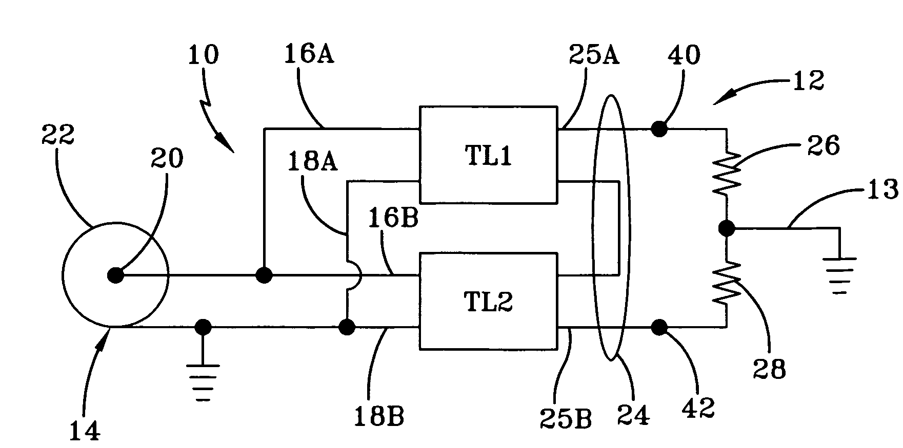
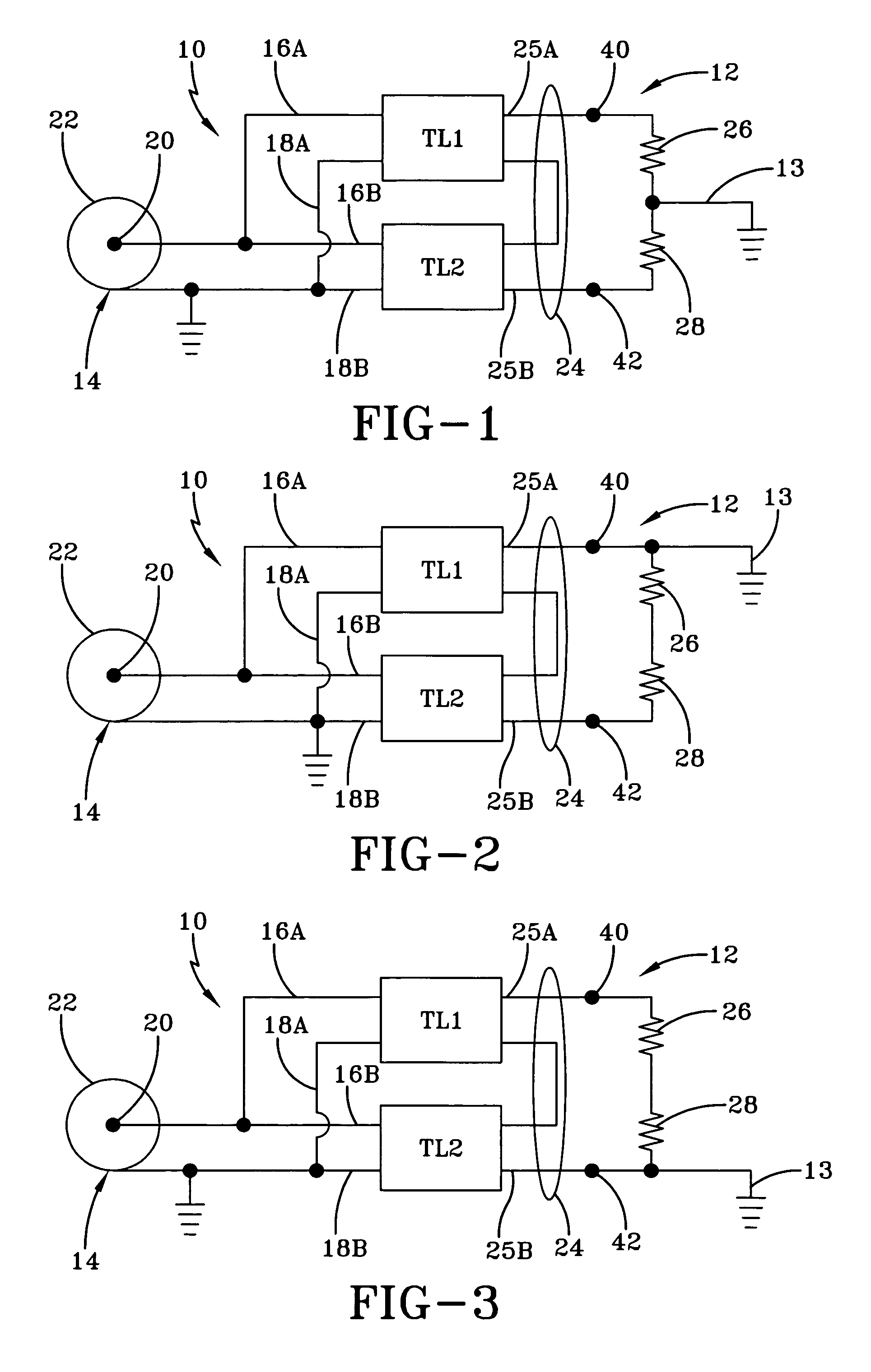
[0020]A typical balun is identified by the numeral 10, as shown in FIGS. 1-3, and is used to couple a balanced dipole antenna 12 with an unbalanced feedline 14. Balun 10 includes two transmission line transformers referred to as TL1 and TL2. Typically, transmission line transformer TL1 and TL2 are created to have the same structural and operational characteristics. Thus, they can be said to be equivalent. However, because of the typical arrangement of transmission line transformer TL1 and TL2 with respect to the feedline 14 and antenna 12, transmission line transformer TL1 is subjected only to a portion of the common mode voltage, magnetic flux intensity, and other electromagnetic stresses that transmission line transformer TL2 is subjected to.

[0021]FIGS. 1-3 illustrate the ideal, and worst case conditions under which the balun 10 may operate. In FIG. 1, a perfectly balanced antenna 12 is shown in which the 500V signal received by the antenna 12 is equally distributed with respect t...


PUM


Abstract

The present antenna system includes a balun for coupling an antenna to a feed line. The balun has at least two transmission line transformers, such that the transmission line transformers are coupled in parallel at their inputs with the feedline, and coupled in series at their outputs with the antenna. At least one of the transmission line transformers maintained by the balun is fabricated so that it has reduced power dissipation properties, and reduced electromagnetic stress handling properties with respect to the other transmission line transformers. Such considerations reduce fabrication time, waste of material, and the cost of the balun.

Description

CROSS-REFERENCE TO RELATED APPLICATION[0001]This application claims the benefit of U.S. Provisional Application No. 60 / 718,008, filed Sep. 19, 2005. The specification of the above-referenced application is incorporated herein by reference.TECHNICAL FIELD[0002]The present invention relates to an antenna balun utilizing a pair of transmission line transformers. More specifically, the present invention is directed to a balun in which the power dissipation capacity of each of the transmission line transformers is unequal. More particularly, the present invention relates to a balun in which the electromagnetic handling capacity of each of the transmission line transformers is unequal.BACKGROUND ART[0003]Baluns are used to interface balanced systems to unbalanced systems, and to transition electrical energy therebetween. In fact, the word “balun” is derived from the “bal” of balanced and the “un” of unbalanced. Many antennas interface with an unbalanced feedline, such as a coaxial cable. ...

Claims


Application Information

Patent Timeline
Patent Type & Authority Patents(United States)
IPC IPC(8): H03H7/42H03H7/38
CPCH01P5/10
Inventor RAUCH, CHARLES T.
Owner PDS ELECTRONICS
Why Eureka
Try Eureka