Eureka AIR delivers breakthrough ideas for toughest innovation challenges, trusted by R&D personnel around the world.

Laser irradiation system

a laser irradiation and laser technology, applied in the field of laser irradiation systems, can solve the problems of insufficient simple light emission from leds, failure to permit users, and inability to observe the situation, so as to achieve the effect of easy observation

Inactive Publication Date: 2009-08-25
SONY CORP
View PDF21 Cites 3 Cited by
  • Summary
  • Abstract
  • Description
  • Claims
  • Application Information

AI Technical Summary

Benefits of technology

[0007]Thus, there is a need for providing a laser irradiation system capable of clearly indicating that irradiation with laser is under way, for the user to easily notice the situation even in the case of unintended irradiation with laser.
[0011]According to the laser irradiation system of the present invention, it is possible to clearly indicating that irradiation with laser is under way, for the user to easily notice the situation even in the case of unintended irradiation with laser.

Problems solved by technology

However, as a result of investigations of whether the LED indicator in practical use can clearly inform the user of the fact that irradiation is under way, there have been found some cases where the simple light emission from the LED is insufficient.
For example, unintended irradiation with laser may be continued due to an erroneous operation, and, in such a case, the simple light emission from the LED alone may fail to permit the user to notice the situation.
In addition, simple provision of the LED alone may fail to give an anesthetic appeal.

Method used


Image

  • Laser irradiation system
  • Laser irradiation system
  • Laser irradiation system

Examples


first embodiment

[0017]Now, preferred embodiments of the present invention will be describe in detail below referring to the drawings. Here, a laser pointer for indicating an object body (target) in a lecture, a lecture meeting or the like by a laser beam will be described as an embodiment; however, the present invention is not limited to the laser pointer, and is applicable generally to laser irradiation systems for displaying characters or figures by irradiating an external target with a laser beam.

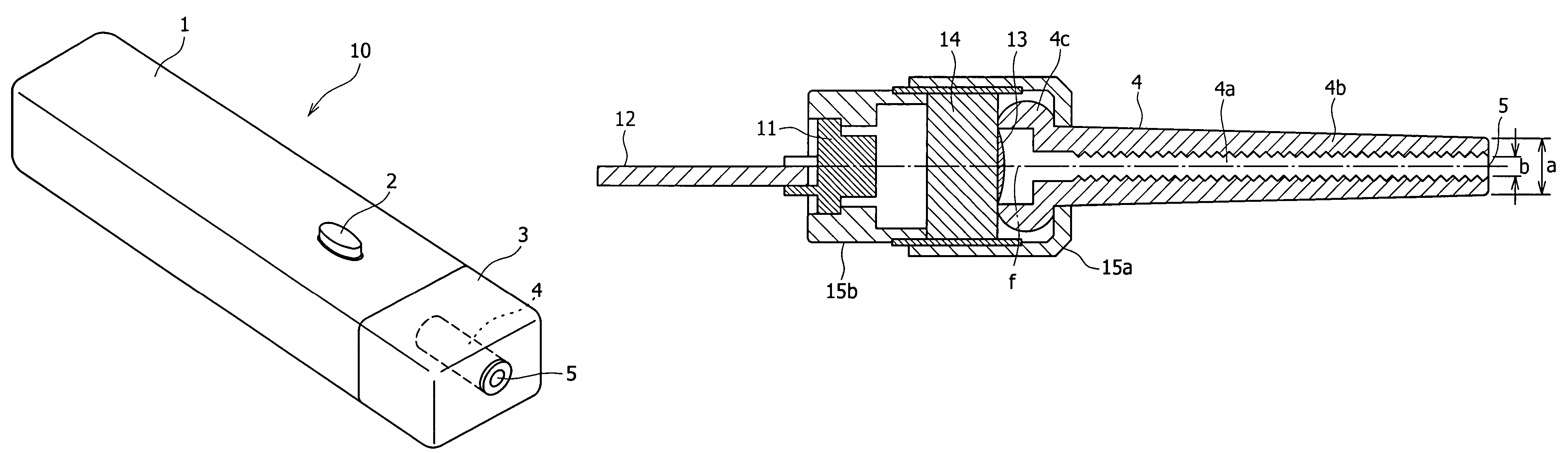
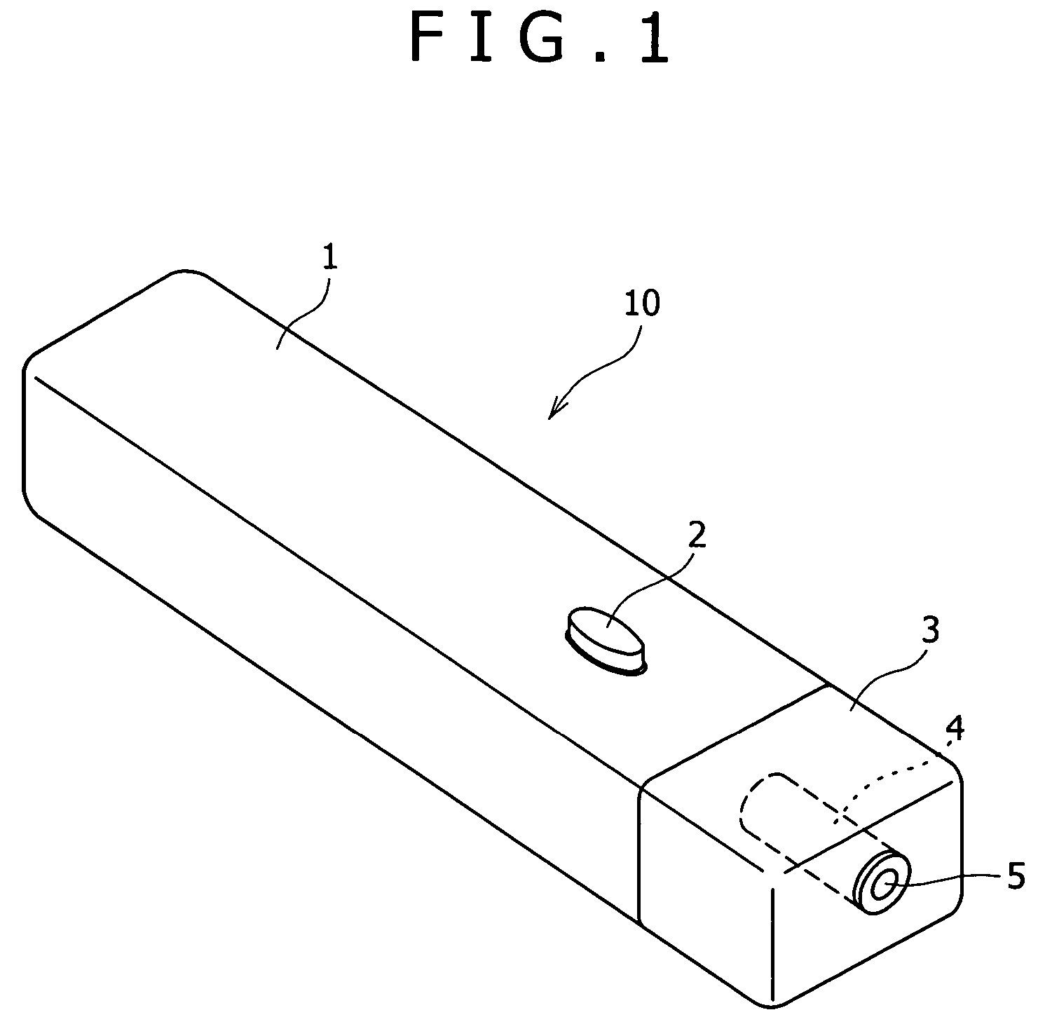
[0018]FIG. 1 is a perspective view showing the appearance of a laser pointer 10 according to this embodiment. The laser pointer 10 in this embodiment has a main body portion case 1 formed in a roughly elongate rectangular parallelopiped shape. The main body portion case 1 is formed of a plastic or the like material, and a laser irradiation button 2 is formed on the surface thereof. The main body portion case 1 incorporates therein a laser module for radiating a laser beam, and a cell or battery for driv...

second embodiment

[0030]FIG. 3 shows, as a second embodiment, an exemplary configuration in which a light pipe 4 is formed by use of a light-transmitting resin containing a light scattering agent, in place of processing the inside surface of the light pipe 4 into a rough surface. Symbol 31 in the figure denotes the light scattering agent. As the light scattering agent, for example, aluminum flakes can be used. Laser energy is given also to an outer tube portion 4b in this configuration. As a result, a part of the laser beam incident on the light pipe 4 is discharged to the exterior of the light pipe 4 while being scattered by the light scattering agent 31.

[0031]This configuration eliminates the need to process the inside surface of the light pipe 4 into a rough surface.

[0032]In addition, for obtaining effective light emission, it may be contemplated to combine the first embodiment and the second embodiment. Namely, there may be adopted a configuration in which the light pipe 4 is formed by use of a l...

third embodiment

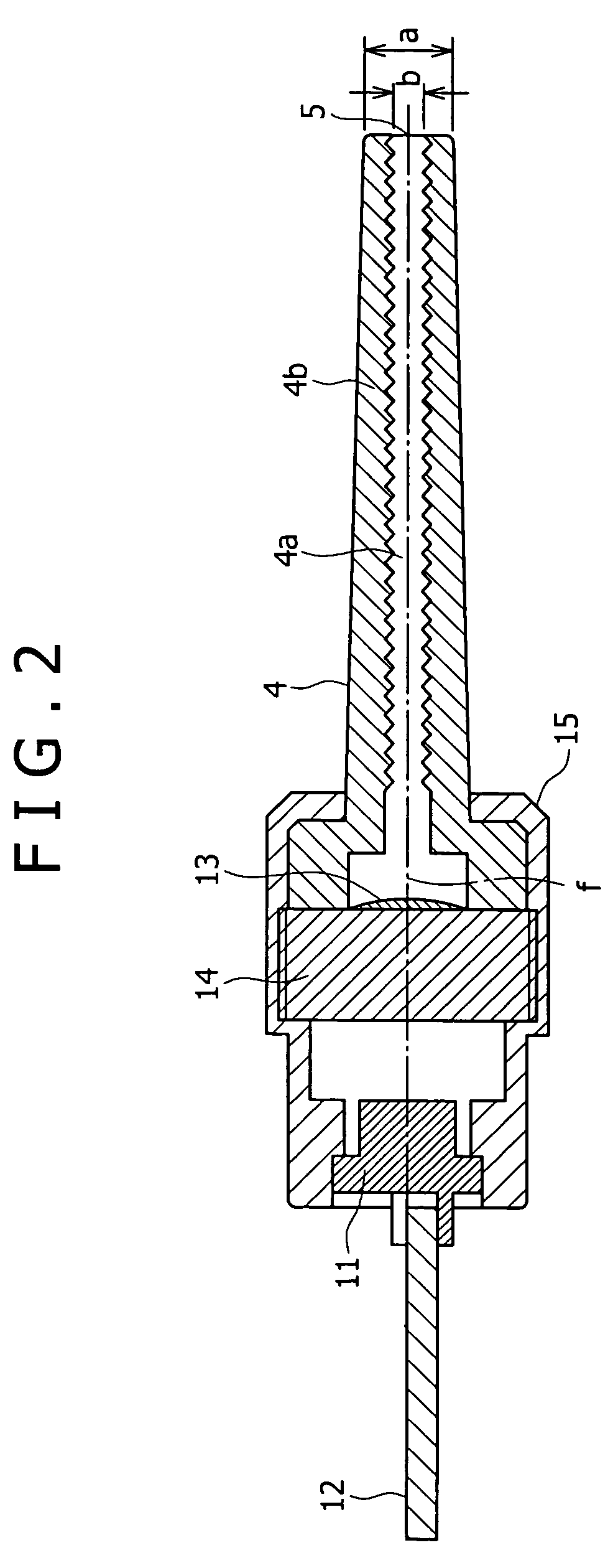
[0033]In the above-described embodiments, the laser light is scattered in order to obtain effective light emission, by processing the inside surface of the light pipe into a rough surface (first embodiment) or by forming the light pipe by use of a resin containing a light scattering agent such as aluminum flakes (second embodiment). As a third embodiment, there may be adopted a configuration in which the light pipe 4 is formed of a pigment-containing resin, and the diameter of the lens 13 is set to be not less than the outside diameter a of the light pipe, so as to give the laser energy to not only the hollow portion 4a but also the outer tube portion 4b. It has been empirically confirmed that such a configuration can provide effective light emission from the light pipe. The third embodiment is advantageous in that it is unnecessary to process the inside surface of the light pipe into a rough surface or to use a resin containing a light scattering agent.


PUM


Abstract

A laser irradiation system includes a laser diode as a laser generation source, a lens for receiving the laser light introduced thereto from the laser diode and producing a laser beam, and a light pipe for receiving the laser beam produced by the lens and introduced thereto, wherein the light pipe has a hollow portion for guiding the introduced laser beam for irradiation therewith, and an outer tube portion for emitting light by scattering the introduced laser beam, whereby the irradiation with laser being conducted can be clearly indicated so that the user can easily notice the situation even in the cases of unintended irradiation with laser.

Description

BACKGROUND OF THE INVENTION[0001]The present invention relates to a laser irradiation system for displaying characters or figures by irradiating an external member with a laser beam.[0002]Laser pointers for indicating an objective body by a laser beam in a lecture, a lecture meeting and the like have been manufactured and sold (see, for example, Japanese Patent Laid-open No. 2004-20604). At present, portable laser applied apparatuses including such a laser pointer are designated as products to be regulated by the consumer livelihood product safety regulation, and it is a duty for the manufacturers to manufacture products which conform to the technical standards.[0003]As the technical standards, a variety of items have been determined from the viewpoint of safety, and one of the items is that “the product should have a function for enabling the user to check that the product is being supplied with electric current”. In short, it is a duty for the manufacturers to add to the products ...

Claims


Application Information

Patent Timeline
Patent Type & Authority Patents(United States)
IPC IPC(8): G02B27/20
CPCG02B27/20
Inventor KAJIKURI, JUNICHIMORI, TAMIOINOUE, HIDEKI
Owner SONY CORP
Why Eureka
Eureka Blog
Learn More