Armature winding of electric rotating machine, stator of electric rotating machine and electric rotating machine

a technology of electric rotating machines and windings, which is applied in the direction of windings, dynamo-electric components, and magnetic circuit shapes/forms/constructions, etc., can solve the problems of increasing current loss and heat generated inside the element wire conductor pair, so as to suppress the increase in loss and local overheat of the armature windings, the effect of reducing the circulation curren

Inactive Publication Date: 2009-08-25
KK TOSHIBA
View PDF15 Cites 0 Cited by
  • Summary
  • Abstract
  • Description
  • Claims
  • Application Information

AI Technical Summary

Benefits of technology

[0025]A second aspect of the present invention provides a stator of an electric rotating machine, comprising a stator core provided with a plurality of ventilation ducts in a radial direction and a plurality of winding slots in an axial direction; and an armature winding in which at least one armature winding bar is mounted in one of the winding slots, the bar being composed of a plurality of element wire conductors stacked in the winding slot, at least one of the element wire conductors being formed so as to be twisted and transposed along an extension direction of the winding slot, the element wire conductors being short-circuited at both ends protruded outside from both side ends of the stator core, transposing pitches of the portion of the element wire conductor enclosed in the winding slot being different from each other at a proximity of both ends and at a middle zone of the winding slot, a total transposing angle being approximately 540 degrees, wherein a subsidiary core portion including a portion having a different core space factor is provided so as to reduce an unbalanced voltage generated at both ends of the element wiring conductor due to a difference in magnetic fluxes interlinking at the element wire conductor.
[0027]A fourth aspect of the present invention provides a stator of an electric rotating machine, comprising a stator core provided with a plurality of ventilation ducts in a radial direction and a plurality of winding slots in an axial direction; and an armature winding having at least one armature winding bar composed of a plurality of element wire conductors stacked in a winding slot, one of the element wire conductors being formed so as to be twisted and transposed along an extension direction of the winding slot, the element wire conductors being short-circuited at both sides protruding outside from both side ends of the stator core, transposing pitches of the element wire conductor provided in the winding slot being different from each other between a proximity of both border zones and a middle zone of the winding slot, an entire transposing angle being substantially 540 degrees, wherein, at an end portion of the stator core in an axial direction thereof which is more outside than a portion at which a transposing of the element wire conductor is performed, a subsidiary core portion is provided so as to reduce an unbalanced voltage generated between the element wire conductors, the voltage being generated at both ends of the armature winding due to a difference in magnetic fluxes interlinking at the element wire conductor.
[0028]According to a further aspect of the present invention, there is provided an armature winding of an electric rotating machine, a stator of the electric rotating machine, and the electric rotating machine capable of reducing a circulation current in a closed circuit formed of the element wire conductors exerted by a difference in magnetic flux interlinking to the element wiring conductors and capable of suppressing an increase in loss and local overheat of the armature winding.

Problems solved by technology

If very large voltages are induced between a pair of element wire conductors in the half coil, for example, a large circulation current, i.e., a current circulating along a closed loop circuit formed by an element wire conductor pair flows, and then, a current loss increases and heat generated inside the element wire conductor pair also increases.

Method used


Image

  • Armature winding of electric rotating machine, stator of electric rotating machine and electric rotating machine
  • Armature winding of electric rotating machine, stator of electric rotating machine and electric rotating machine
  • Armature winding of electric rotating machine, stator of electric rotating machine and electric rotating machine

Examples


first embodiment

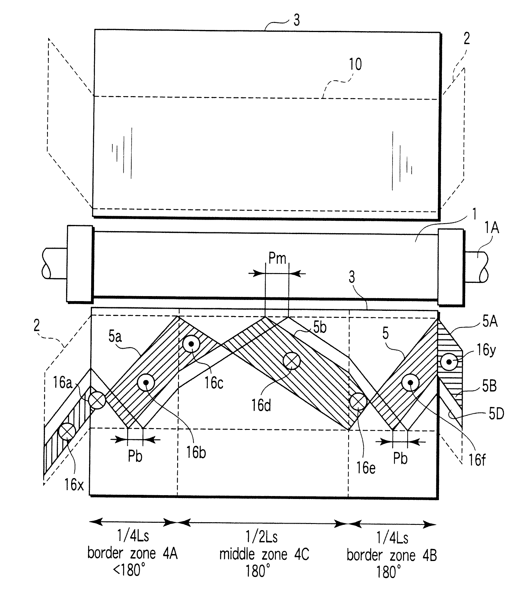
[0062]First, a first embodiment will be described with reference to FIG. 1. The configuration of the electric rotating machine according to the first embodiment of the present invention is shown in FIG. 1, which is composed of: a rotor 1; a stator core 3 having a plurality of winding slots 10 extending along a rotating axis of the rotor 1; and an armature winding 2 embedded in the winding slots 10. The armature winding 2 is equipped with at least one armature winding bar composed of a number of stacked element wire conductors or strands. For example, as shown in FIG. 25A, the armature winding bar is composed of top coil unit 2c and bottom coil unit 2d stacked in the slot 10 having a wedge 3A provided at an opening of the slot 10 for holding the coil units 2c and 2d in the slot 10.

[0063]In the embodiment of FIG. 1, Three strands or conductors 5A, 5B and 5D provided in the armature winding 2 are continuously twisted along the extension direction in the stator core 3 at portions provid...

second embodiment

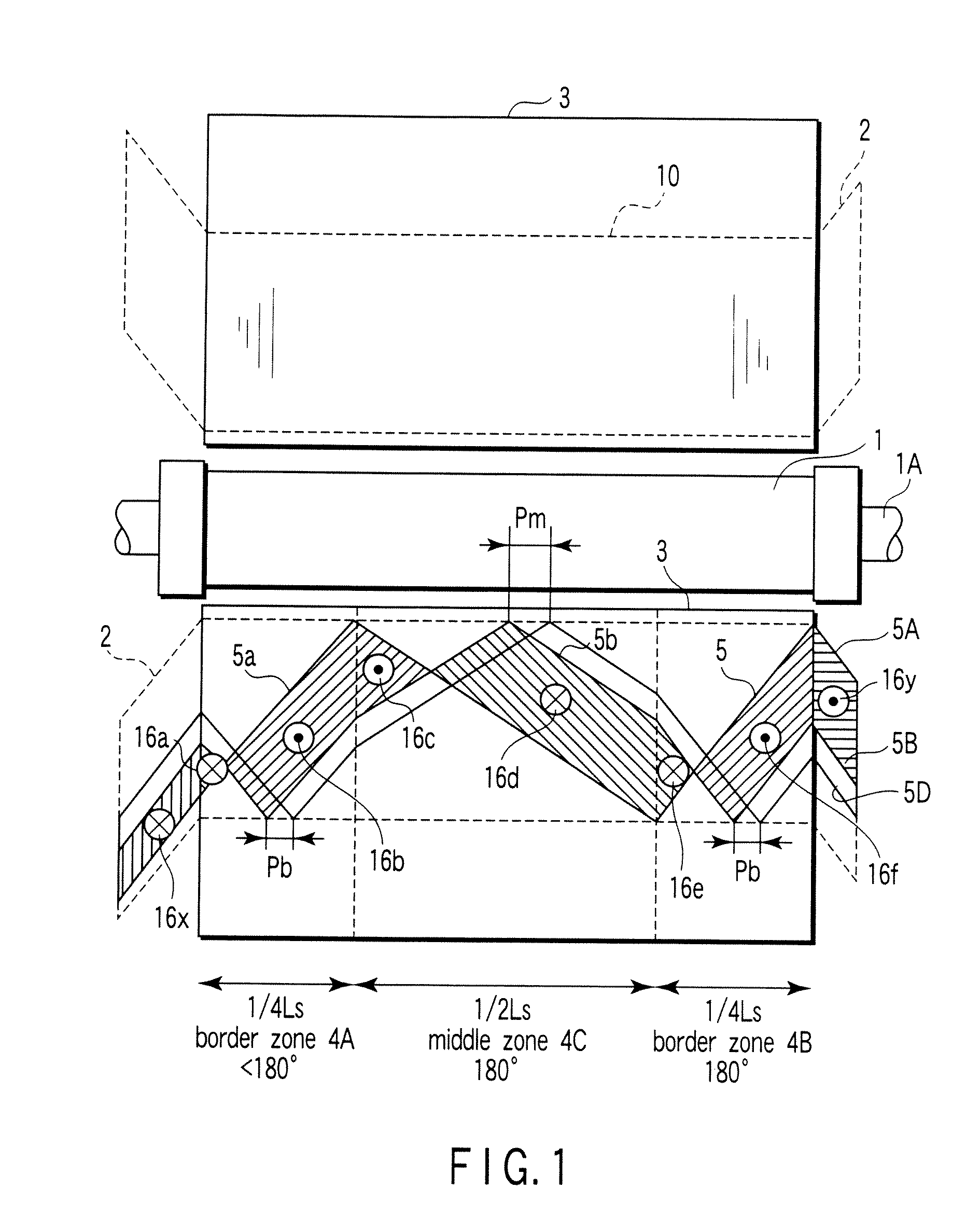
[0082]Next, a second embodiment according to the present invention will be described with reference to FIG. 7. A description is omitted with respect to the constituent elements similar to those shown in FIG. 1.

[0083]In an element wire conductor 5, a 180-degree transposition is made in the range of ¼Ls on the left end border zone 4A of a stator core 3, and further, a 180-degree transposition is made in the range of ½Ls at the middle zone 4C. Furthermore, the transposing angle A in the range of ¼Ls at the right end border zone 4B is greater than 180 degrees, and is set at 190 degrees, for example.

[0084]In the first embodiment, the transposing angle of the left end border zone (core border zone 4A) of the stator core 3 is smaller than 180 degrees. In the second embodiment of FIG. 7, the transposing angle of the right end part (core border zone 4B) of the stator core 3 is set to be greater than 180 degrees in turn. With such a configuration, an interlinking magnetic flux 16e is reduced ...

third embodiment

[0092]Next, a third embodiment according to the present invention will be described with reference to FIGS. 12 to 13. FIG. 12 is a view showing a relationship between an element wire conductor 5A and an interlinking magnetic flux 16a to 16f, 16x and 16y. FIG. 13 shows a side view of a configuration in which a conventional stator core is provided with a subsidiary core portion 14 and a ventilation duct 4 in a stator core 3.

[0093]The subsidiary core portion 14 is provided at the illustrative right end part of the stator core 3 such that a core space factor of the portion 14 is greater than those of other stator core portions. An element wire conductor 5A is continuously twisted toward the extension direction of a wiring slot 10 and is formed so as to be transposed at 540 degrees at an active portion in the wiring slot 10. The element wire conductor 5A and the other conductor 5B forming a conductor pair is short-circuited at both sides of an armature winding 2 that protrudes to the out...


PUM


Abstract

An armature winding of an electric rotating machine is provided, which includes at least one armature winding bar composed of a plurality of element wire conductors, wherein the armature winding bar includes an element wire conductor configured to have twisted transposing angles of 180 degrees at one border zone and a middle zone in a winding slot and a twisted transposing angle different from 180 degrees at the other border zone of the winding slot of the element wire conductor.

Description

CROSS-REFERENCE TO RELATED APPLICATIONS[0001]This application is based upon and claims the benefit of priority from prior Japanese Patent Application No. 2006-305885, filed Nov. 10, 2006, the entire contents of which are incorporated herein by reference.BACKGROUND OF THE INVENTION[0002]1. Field of the Invention[0003]The present invention relates to an electric rotating machine, a stator of the electric rotating machine, and an armature winding of the electric rotating machine.[0004]2. Description of the Related Art[0005]A stator of an electric rotating machine is configured as shown in FIG. 25A. FIG. 25A is a sectional view showing a part of the stator of the electric rotating machine wherein a plurality of winding slots 10 are formed in the core 3 of the stator configured with a stacked iron plates and an armature winding 2 is mounted in each winding slot 10. The winding slots 10 are formed in the core 3 in a direction extending along a rotating axis of a rotor (not shown) and a pl...

Claims


Application Information

Patent Timeline
Patent Type & Authority Patents(United States)
IPC IPC(8): H02K17/00
CPCH02K1/16H02K3/14
Inventor FUJITA, MASAFUMITOKUMASU, TADASHIKAKIUCHI, MIKIO
Owner KK TOSHIBA
Why Eureka
Try Eureka