Multipurpose tooth paste dispenser

a multi-purpose, dispenser technology, applied in the field of dispensers, can solve the problems of toothpaste waste, large loss of tube contents, and spoilage of the general appearance and neatness of the room, and achieve the effect of maintaining a sanitary condition

Inactive Publication Date: 2009-09-01
THOMAS JOSHUA J
View PDF15 Cites 3 Cited by
  • Summary
  • Abstract
  • Description
  • Claims
  • Application Information

AI Technical Summary

Benefits of technology

[0013]Using the embodying the present invention will permit all of the toothpaste from a tube to be used and at measured quantities. An aesthetically pleasing housing will contain the tube and the mechanism so that unsightly, partially used, twisted toothpaste tubes will not be left on a surface. Toothpaste can be dispensed without requiring the tube nozzle to touch a toothbrush thereby maintaining a sanitary condition which is not likely to pass germs from one person to another if there are multiple users.

Problems solved by technology

This process works fairly well; however, hand squeezing of such tubes to discharge the required quantity of the tube's contents often results in a badly twisted messed up partly full tube always lying in full view on top of bathroom equipment, thus spoiling the general appearance and neatness of the room.
Furthermore, in many cases, the squeezing of the tube is done by careless adults or children, so that a great deal of the tube's contents is lost when the tube is discarded.
Furthermore, children have a tendency not to squeeze the tube from the end opposite the mouth, and the result is wasted toothpaste.
Leakage can also result from this type of squeezing because creases tend to turn up in parts of the tube that still contain toothpaste.
The inventor has found that toothpaste tubes often become badly twisted which may cause a cracking of the tube wall thus resulting in loss of the product through the cracks when the tube is squeezed.
It is not uncommon to find unsightly partially-squeezed tubes of toothpaste in bathrooms.
Oftentimes, these partially-squeezed tubes are found on the bathroom counter, giving the bathroom a cluttered or messy appearance.
In addition, it has been observed that a twisted tube cannot be squeezed sufficiently so as to completely expel the contents thereof thus resulting in the tube being discarded prior to complete evacuation.
Another concern with hand-squeezed toothpaste tubes is that the amount of toothpaste administered at each brushing is inconsistent.
Furthermore, the time actually spent brushing varies from brushing to brushing and may often be less than the dentist-recommended time.
Yet another problem with hand-squeezing of toothpaste tubes is that as they are emptied, it becomes increasingly difficult to dispense toothpaste, and nine out of ten times the tube is discarded before all of the toothpaste is used.
Both the over-administration of toothpaste and the difficulty of emptying the tube of toothpaste results in toothpaste being wasted.
Some people consider toiletry items, such as toothpaste tubes and toothbrushes, personal and instead of sharing a single toothpaste tube, several toothpaste tubes for each member of the family may necessarily be stored in the bathroom creating additional clutter and storage problems.
However, the plastic material used in the new tubes tends to return to its original shape after it is deformed, thereby essentially making it impossible for the user to roll the bottom of the tube to prevent the paste from being redistributed thereto should the user squeeze at a midpoint of the tube.
Furthermore, it is very annoying to reach for the tube of toothpaste and then find that it is not in its usual spot.
However, these dispensers require the squeezing member to travel along the length of the screw first to dispense product from a container and then reverse its direction along the screw without any work performed other than to return the squeezing member back to its origin.
This requires unproductive time on the part of the user to reconfigure the dispenser for subsequent use.
Further, this type of mechanism is inefficient and causes undue fatigue upon a user's fingers with manually actuated product dispensers and undue stress upon mechanical and electrical parts in an automatically actuated product dispenser, leading to accelerated mechanical and / or electrical failure of prior art product dispensers.
In addition, these dispensers are generally complex in order to accommodate both forward and reverse travel of the squeezing member retained within the frame.
These product dispensers have many moving parts and are not economical to manufacture or repair.
Furthermore, these dispensers tend to be inconsistent in the amount of product dispensed.
These dispensers are often cumbersome to use thereby making them difficult to use by small children or others who may have difficulty in coordinating the use of their hands.

Method used


Image

  • Multipurpose tooth paste dispenser
  • Multipurpose tooth paste dispenser
  • Multipurpose tooth paste dispenser

Examples


Embodiment Construction

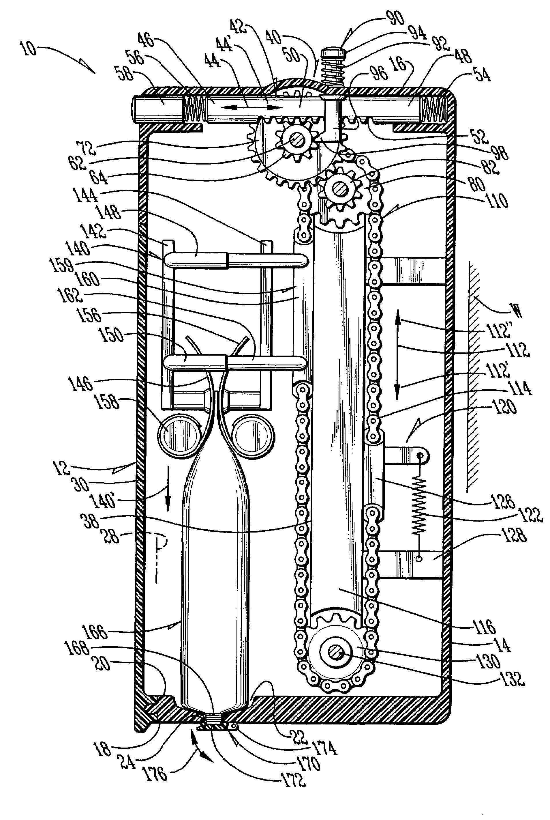
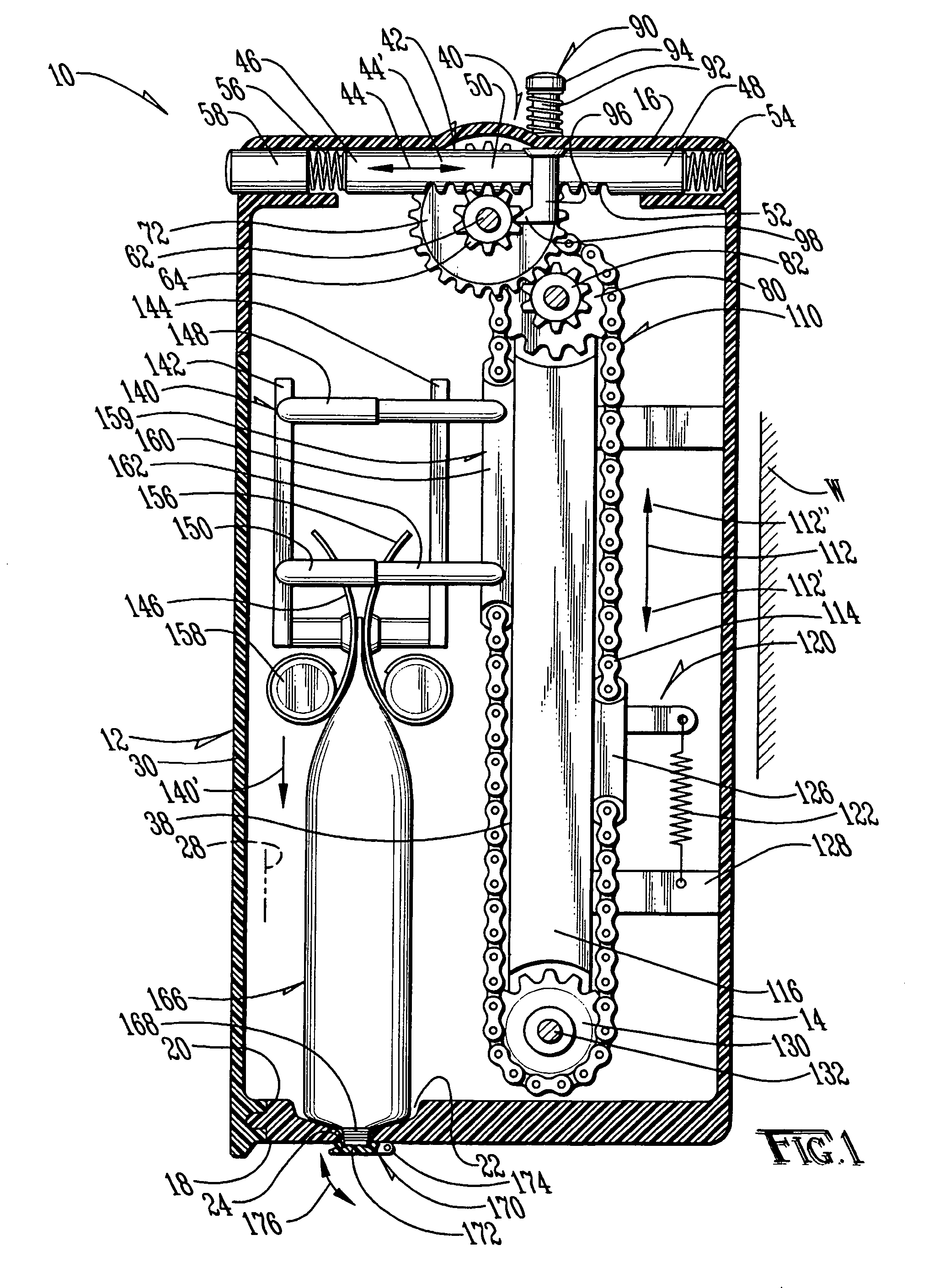
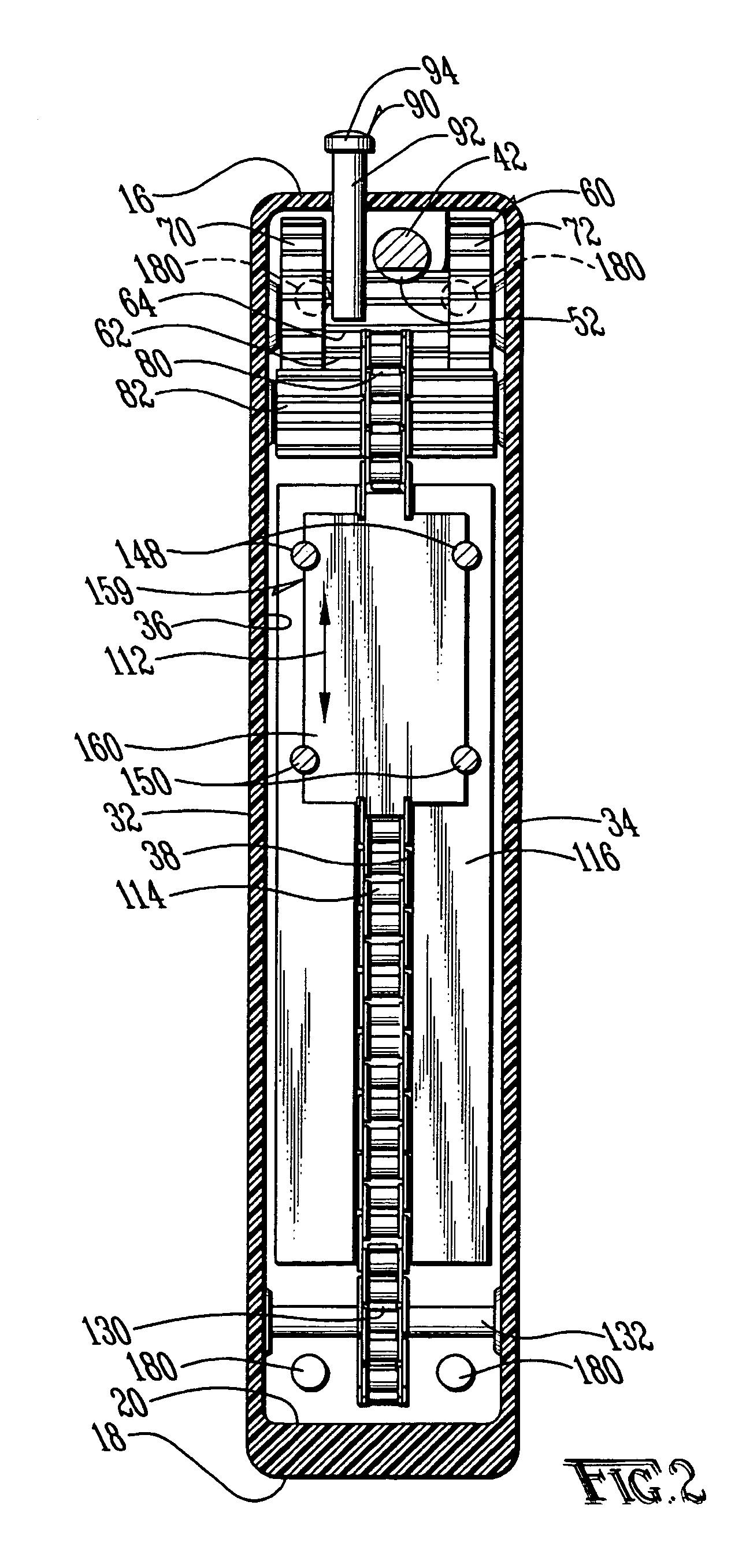
[0022]Referring to the figures, it can be understood that the present invention is embodied in a toothpaste tube squeezing mechanism 10.

[0023]Mechanism 10 comprises a hollow housing 12 which includes a first wall 14 that is a rear wall when the housing is in a use orientation and which can be mounted on a support surface, such as a wall W or the like when the mechanism is in use. Housing 12 further includes a second wall 16 which is a top wall when the housing is in a use orientation such as shown in FIG. 1 and a third wall 18 which is a bottom wall when the housing is in a use orientation. The bottom wall has a first surface 20 which is an inside surface when the housing is in a use orientation, an indentation 22 in the inside surface and a dispensing hole 24 defined therethrough at the indentation. The use of the indentation and dispensing hole will be understood from the following description.

[0024]Housing 12 further includes a longitudinal axis 28 which extends between the top w...


PUM


Abstract

A toothpaste tube squeezing mechanism includes a housing in which a toothpaste tube is stored and a button which is pushed to dispense toothpaste from the tube. The button is connected to a tube squeezing mechanism by a gear system.

Description

TECHNICAL FIELD OF THE INVENTION[0001]The present invention relates to the general art of dispensing, and to the particular field of mechanisms for dispensing material, such as toothpaste, from a tube.TITLE OF THE INVENTION[0002]Toothpaste for consumer use has long been sold in tubes requiring the user to squeeze part of the tube to extract the paste from a spout at one end of the tube. For many years, the tubes in which the toothpaste was distributed were fabricated from a malleable metal thereby permitting the user to readily extract the paste. In order to efficiently extract the maximum amount of paste from the tube, the user needed to progressively squeeze the tube from the bottom of the tube to the tube spout. As the tube was squeezed from the bottom, the metal tube could be rolled toward the tube spout, thereby effectively preventing the paste from being redistributed to the bottom of the tube should the user squeeze at a midpoint of the tube.[0003]This process works fairly we...

Claims


Application Information

Patent Timeline
Patent Type & Authority Patents(United States)
IPC IPC(8): B65D35/28
CPCB65D35/28
Inventor THOMAS, JOSHUA J.
Owner THOMAS JOSHUA J
Why Eureka
Try Eureka