
Starting system for salient-poled-rotor electric motor

a technology of electric motors and starting systems, applied in the field of electric motors, can solve the problems of poor starting torque, poor running characteristics, and slight unbalancing of attractive magnetic forces, and achieve the effect of substantially maxim substantially minimizing the torque between the rotor and the stator

Inactive Publication Date: 2009-09-01
TRI SEVEN RES
View PDF17 Cites 18 Cited by
  • Summary
  • Abstract
  • Description
  • Claims
  • Application Information

AI Technical Summary

Benefits of technology

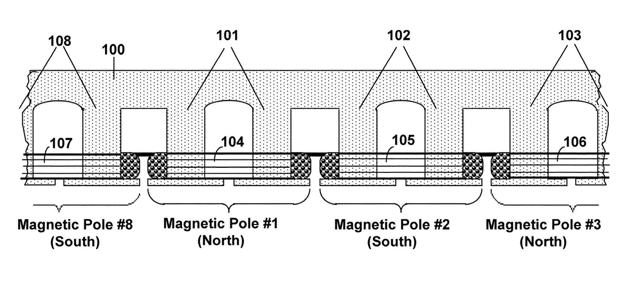
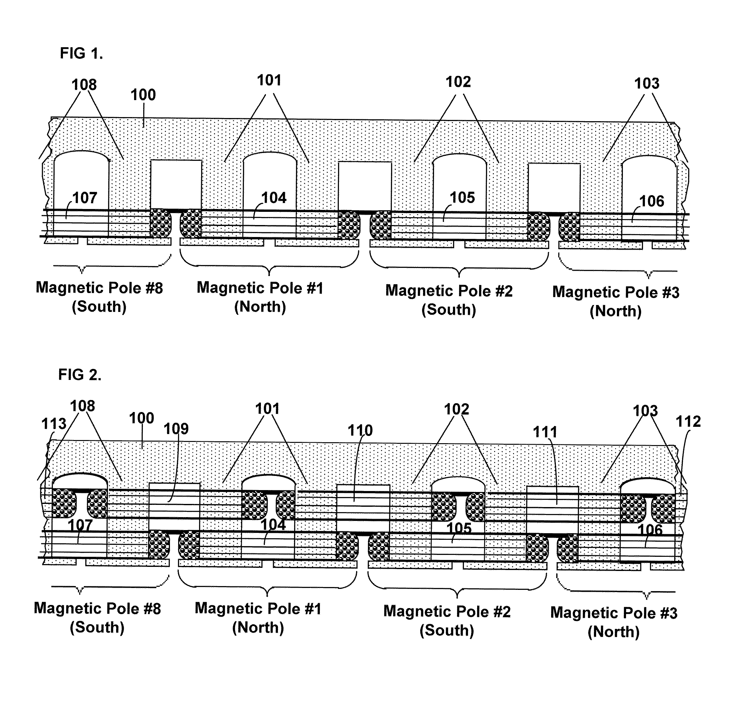
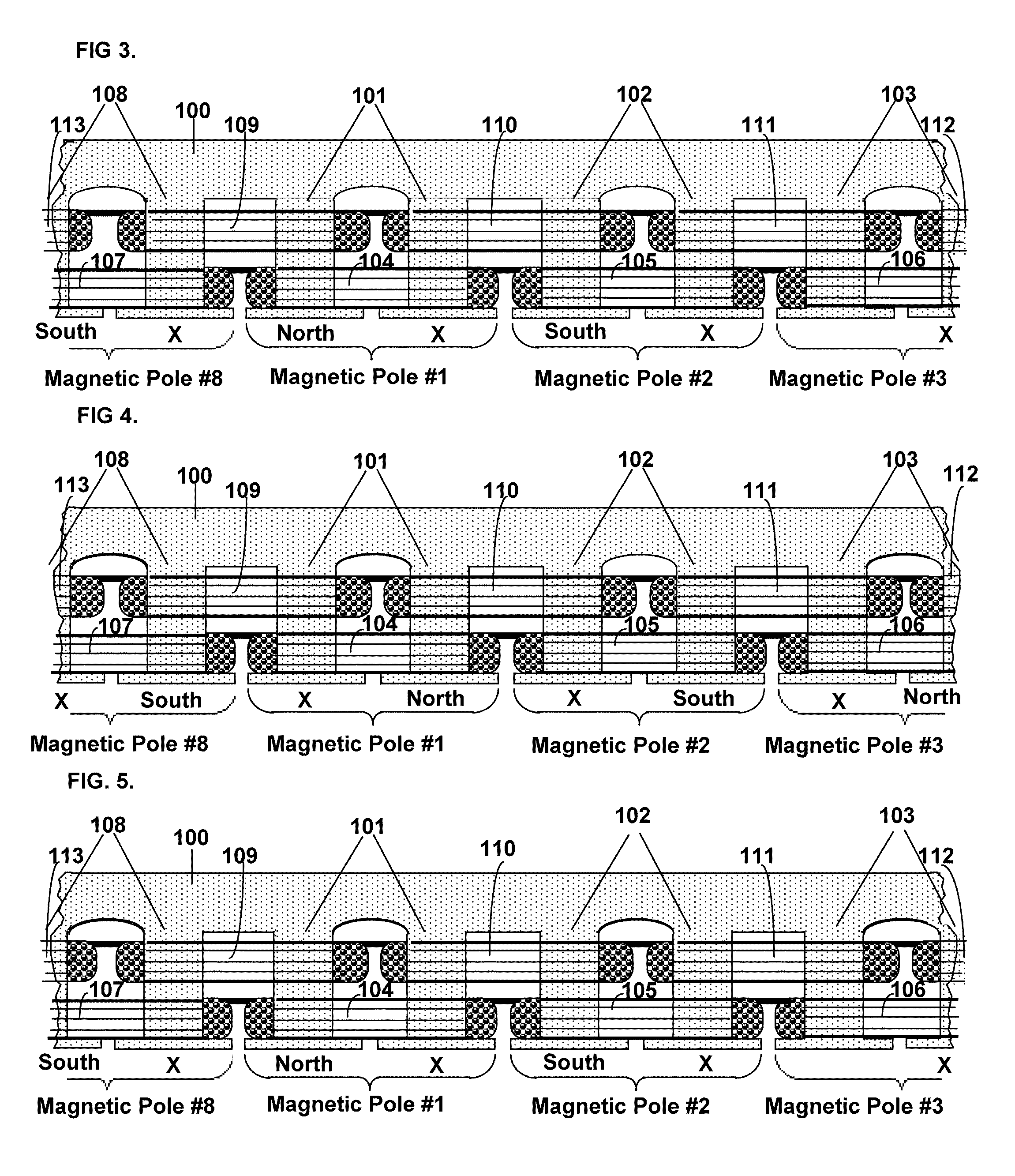
[0008]The present invention further provides a starting system and method for starting a salient-poled-rotor electric motor having a stator with a plurality of spaced salient poles, a plurality of field coils of unchanging polarity, and a plurality of armature coils, wherein each field coil of the plurality of field coils at least partially overlaps an armature coil of the plurality of armature coils, and wherein variable excitement of the armature coils alternately creates a magnetic pole force in every other pole of the plurality of spaced salient poles of the stator. In such motors, the stator has a first position, wherein the rotor is in stasis with respect to the stator and torque between the rotor and the stator is substantially minimized, and a second position, wherein torque between the rotor and the stator is substantially maximized. A drive circuit provides current to the field coils and the armature coils. A start circuit is provided for regulating the drive circuit to vibrate the rotor to the second position. A current source is connectable to the drive circuit for variably exciting the armature coils to produce substantially continuous rotation of the rotor. A switch is provided for electrically engaging the start circuit with the drive circuit while the rotor moves from the first position to the second position, and for electrically engaging the current source with the drive circuit when the rotor reaches the second position.

Problems solved by technology

In electric motors which have no coils or induction bands, successfully starting the motor under heavy loads can present some unique challenges.
The result is often only a vibrating rotor unable to achieve enough torque to move against the load.
Although this creates a slight unbalancing of the attractive magnetic forces when the rotor poles are fully registered with the stator poles, the neutral position has only been moved, not eliminated.
Accordingly, this type of shaped pole motor is essentially mono-directional, because it creates poor starting torque and poor running characteristics in the direction of rotation opposite the direction in which the poles are slanted.
Even at its best, the pole shaping method used by Walters provides poor starting torque characteristics in applications where the motor is started under load.
However, if the motor must be started under heavy load, previously known control circuits will not be able to start the motor if the rotor has stopped in the minimum torque position.

Method used


Image

  • Starting system for salient-poled-rotor electric motor
  • Starting system for salient-poled-rotor electric motor
  • Starting system for salient-poled-rotor electric motor

Examples


Embodiment Construction

[0035]Referring to the drawings, the present invention will now be described in detail with reference to the disclosed embodiment.

[0036]In this disclosure, the effect of the invention will be called the Field-Match effect. The reason for the use of the word “match” is that it has two near opposite meanings: one which means “to agree, to be alike” (which we will designate “match1”) and another meaning which means “to oppose”, as in a “football match” (which we will designate “match2”). The torque produced by the stator on the rotor of the Split-Pole Field-Match Motor is caused by a unique design in which two coil fields of near equal value are matched on a single stator pole, alternately, in both senses of the word “match”.

[0037]First, they are “matched1” in one part of the electrical phase as like-fields on the same pole which series and causes the pole to exert a magnetomechanical force on a laminated, ferrite, salient poled rotor; then the coils are “matched2” as opposing fields o...


PUM


Abstract

A starting system and method for starting a salient-poled-rotor electric motor having a stator with a plurality of spaced salient poles, a plurality of field coils of unchanging polarity, and a plurality of armature coils, wherein each field coil of the plurality of field coils at least partially overlaps an armature coil of the plurality of armature coils, and wherein variable excitement of the armature coils alternately creates a magnetic pole force in every other pole of the plurality of spaced salient poles of the stator. In such motors, the stator has a first position, wherein the rotor is in stasis with respect to the stator and torque between the rotor and the stator is substantially minimized, and a second position, wherein torque between the rotor and the stator is substantially maximized. A drive circuit provides current to the field coils and the armature coils. A start circuit is provided for regulating the drive circuit to vibrate the rotor to the second position. A current source is connectable to the drive circuit for variably exciting the armature coils to produce substantially continuous rotation of the rotor. A switch is provided for electrically engaging the start circuit with the drive circuit while the rotor moves from the first position to the second position, and for electrically engaging the current source with the drive circuit when the rotor reaches the second position.

Description

CROSS REFERENCE TO RELATED APPLICATIONS[0001]This application is a continuation-in-part of U.S. patent application Ser. No. 10 / 315,845, filed Dec. 10, 2002 now U.S. Pat. No. 7,276,831.FIELD OF THE INVENTION[0002]The invention relates to the field of electric motors having a plurality of magnetic poles wherein the poles are alternately polarized and neutralized to produce rotation of a rotor, and more particularly, the present invention relates to salient-poled-rotor electric motors which have no coils or inductor bands on the rotor. The present invention further relates to start positioning systems for providing maximum starting torque for start-under-load conditions for such motors.BACKGROUND OF THE INVENTION[0003]In electric motors which have no coils or induction bands, successfully starting the motor under heavy loads can present some unique challenges. In the particular class of electric motors discussed herein, referred to herein as salient-poled-rotor electric motors, rotor t...

Claims


Application Information

Patent Timeline
Patent Type & Authority Patents(United States)
IPC IPC(8): H02K1/00
CPCH02K29/03H02P25/08H02P1/163
Inventor DURHAM, GARY L.DURHAM, HAROLD S.
Owner TRI SEVEN RES
Learn More