
Lock mechanism for stage apparatus

a technology of lock mechanism and stage apparatus, which is applied in the direction of mechanical measuring arrangement, printing, instruments, etc., can solve the problems of inability to lock the movable stage, the size of the driving device of the lock mechanism needs to be increased, and the size of the lock mechanism and the stage apparatus

Inactive Publication Date: 2009-09-01
RICOH IMAGING COMPANY
View PDF3 Cites 4 Cited by
  • Summary
  • Abstract
  • Description
  • Claims
  • Application Information

AI Technical Summary

Benefits of technology

"The present invention provides a lock mechanism for a stage apparatus that can securely lock a movable stage without requiring a large driving force and can prevent the movable stage from being rotated when in a locked state. The lock mechanism includes a pair of engaging members that lock with a pair of arm members when the movable stage is in a non-operational state. A lock driving device rotates the arm members to the engaged position, and an unlock driving device rotates the arm members to the disengaged position. A slide plate is movable between the engaged position and the disengaged position in a direction parallel to a stationary support board. A biasing device is provided on each arm member to rotationally bias it towards the disengaged position. The lock mechanism is simple and can reduce manufacturing costs."

Problems solved by technology

However, in order for the first and second abutting members to contact the cylindrical boss with a strong force, the size of the driving device of the lock mechanism needs to be increased, which undesirably increases the size of the lock mechanism and the stage apparatus.
Furthermore, in the case where this lock mechanism of the prior art is applied to a camera-shake (hand-shake) correction apparatus which corrects ‘rotational shake’, an additional problem occurs.
However, in the above described lock mechanism of the prior art, since there is only one boss (i.e., the cylindrical boss), even if the first and second abutting members clasp this boss, the movable stage cannot be locked so as to be prevented from being rotated.

Method used


Image

  • Lock mechanism for stage apparatus
  • Lock mechanism for stage apparatus
  • Lock mechanism for stage apparatus

Examples


Embodiment Construction

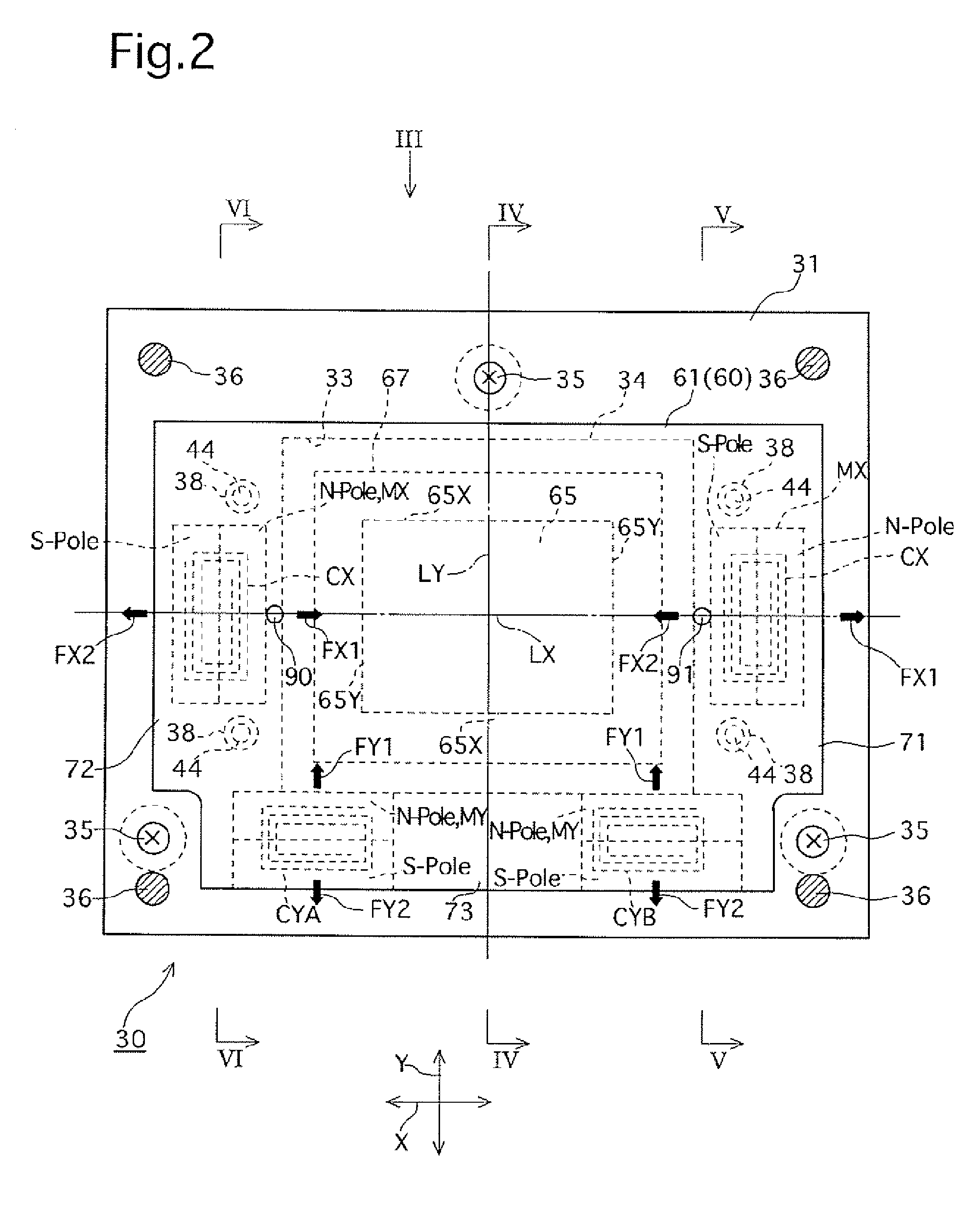
[0035]An embodiment of the present invention will be described hereinafter with reference to the drawings. In the following description, as shown by the arrows in FIGS. 1 and 2, the left / right direction, the upward / downward direction, and the forward / rearward direction of a camera-shake correction apparatus (hand-shake correction apparatus / stage apparatus) 30 is defined as the x-direction, the Y-direction and the Z-direction, respectively.

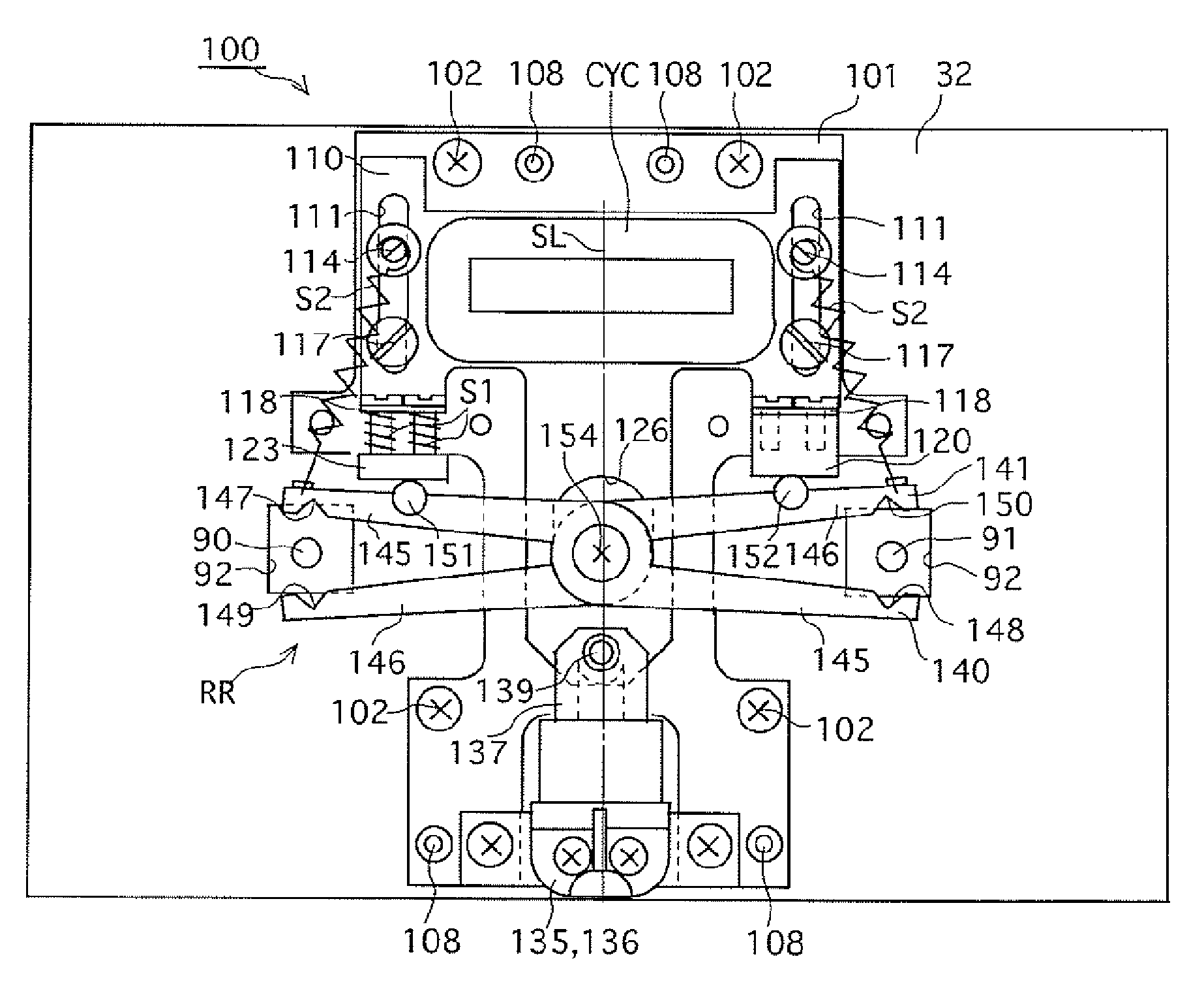
[0036]Firstly the camera-shake correction apparatus 30, which has a lock mechanism 100 of the present invention installed therein, will be described.

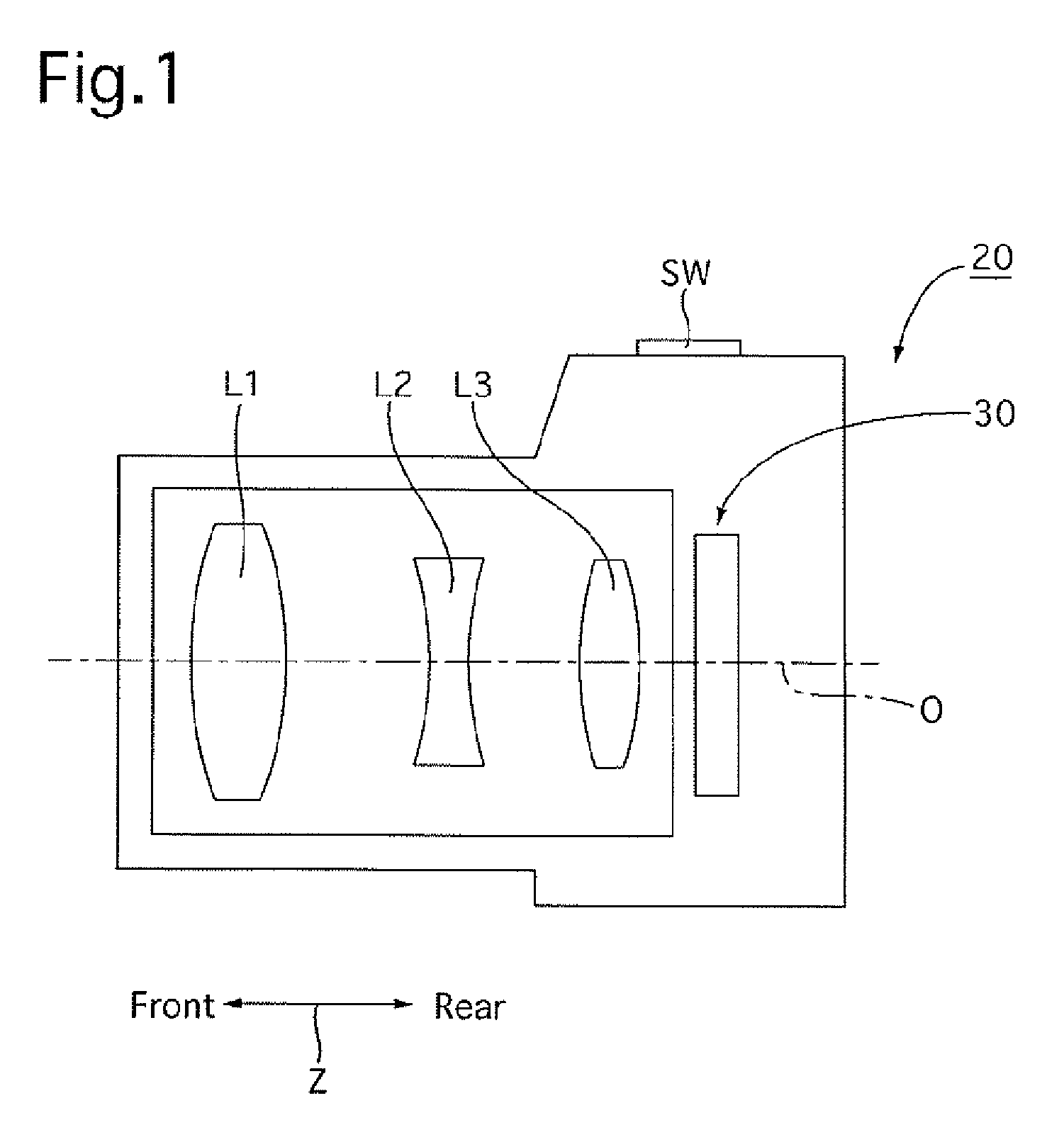
[0037]As shown in FIG. 1, an optical system having first, second and third lens groups L1, L2 and L3, is provided in a digital camera 20, and the camera-shake correction apparatus 30 is provided behind the third lens group L3.

[0038]The camera-shake correction apparatus 30 has a construction as shown in FIGS. 2 through 6. As shown in FIGS. 2 through 6, the camera-shake correction: apparatus 30 is provid...


PUM


Abstract

A lock mechanism for a stage apparatus, the stage apparatus having a stationary support board and a movable stage relatively movable in a plane parallel to the stationary support board, includes a pair of engaging members projecting from the movable stage; a rotational lock device including a pair of arm members rotatably mounted and relatively rotatable between an engaged position at which facing free ends of the arm members clasp corresponding engaging members, and a disengaged position at which the facing free ends of the arm members move away from the corresponding engaging members; a lock driving device which rotates the arm members to the engaged position upon the movable stage entering a non-operational state; and an unlock driving device which rotates the arm members to the disengaged position so that the movable stage enters an operational state.

Description

BACKGROUND OF THE INVENTION[0001]1. Field of the Invention[0002]The present invention relates to a lock mechanism for a stage apparatus which locks a movable stage of the stage apparatus in a non-operational state when the movable stage, which is freely movable along a specific plane, is in a non-operational state.[0003]2. Description of the Prior Art[0004]An example of a lock mechanism for a movable stage, the movable stage being movable in a specific X-direction and a Y-direction orthogonal to the X-direction and to which an image pickup device is fixed on a front surface thereof, is disclosed in Japanese Patent No.3431020. The lock mechanism disclosed therein is provided with one cylindrical boss projecting from the back surface of a movable stage, and first and second abutting members provided behind the movable stage on mutually opposing sides of the cylindrical boss. The first and second abutting members are movable in a direction parallel to the movable stage.[0005]When the m...

Claims


Application Information

Patent Timeline
Patent Type & Authority Patents(United States)
IPC IPC(8): G03B17/00
CPCG03B5/00Y10T292/1028
Inventor HIRUNUMA, KENNEMOTO, SATORU
Owner RICOH IMAGING COMPANY
Learn More