Retrograde osteochondral autograft transfer system

a retrograde osteochondral and autograft technology, applied in the field of surgery, can solve the problems that the tibial plateau and the patella cannot be so easily accessible from the front side, and achieve the effect of reducing the risk of fractur

Active Publication Date: 2009-09-22
ARTHREX
View PDF16 Cites 13 Cited by
  • Summary
  • Abstract
  • Description
  • Claims
  • Application Information

AI Technical Summary

Benefits of technology

The present invention provides a system for transferring healthy bone from one part of the body to another in a way that ensures the bone is implanted in a way that is flush with the surface of the recipient site. This is done using a retrograde method, which involves extracting a healthy bone core from a donor site and then reversing it to align with a similar-sized core in the recipient site. The healthy bone core is then inserted into the recipient site through a tunnel from the underneath of the joint in a retrograde manner. This results in a more natural and flush implantation of the healthy bone.

Problems solved by technology

The technical problem addressed in this patent is the need for a method and apparatus to repair chondral defects on the tibial plateau and patella that are not easily accessible from the front side. The donor plug needs to match the contour of the recipient site for optimal results.

Method used


Image

  • Retrograde osteochondral autograft transfer system
  • Retrograde osteochondral autograft transfer system
  • Retrograde osteochondral autograft transfer system

Examples


Embodiment Construction

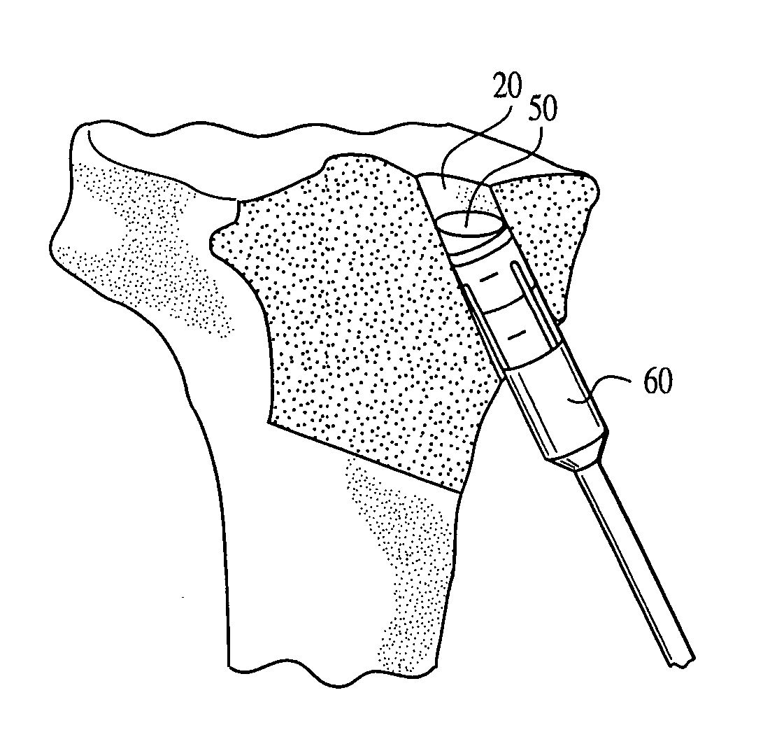
[0034]The present invention provides a method for the osteochondral autograft transfer of a grafted core bone in a retrograde manner as opposed to a conventional anterior manner, so that the grafted core bone is implanted into a recipient damaged site and is flush with the bone surface of the recipient site. The retrograde osteochondral autograft transfer system of the present invention employs two harvesters which have the same size and which are aligned with each other for the retrograde delivery of the grafted core bone.

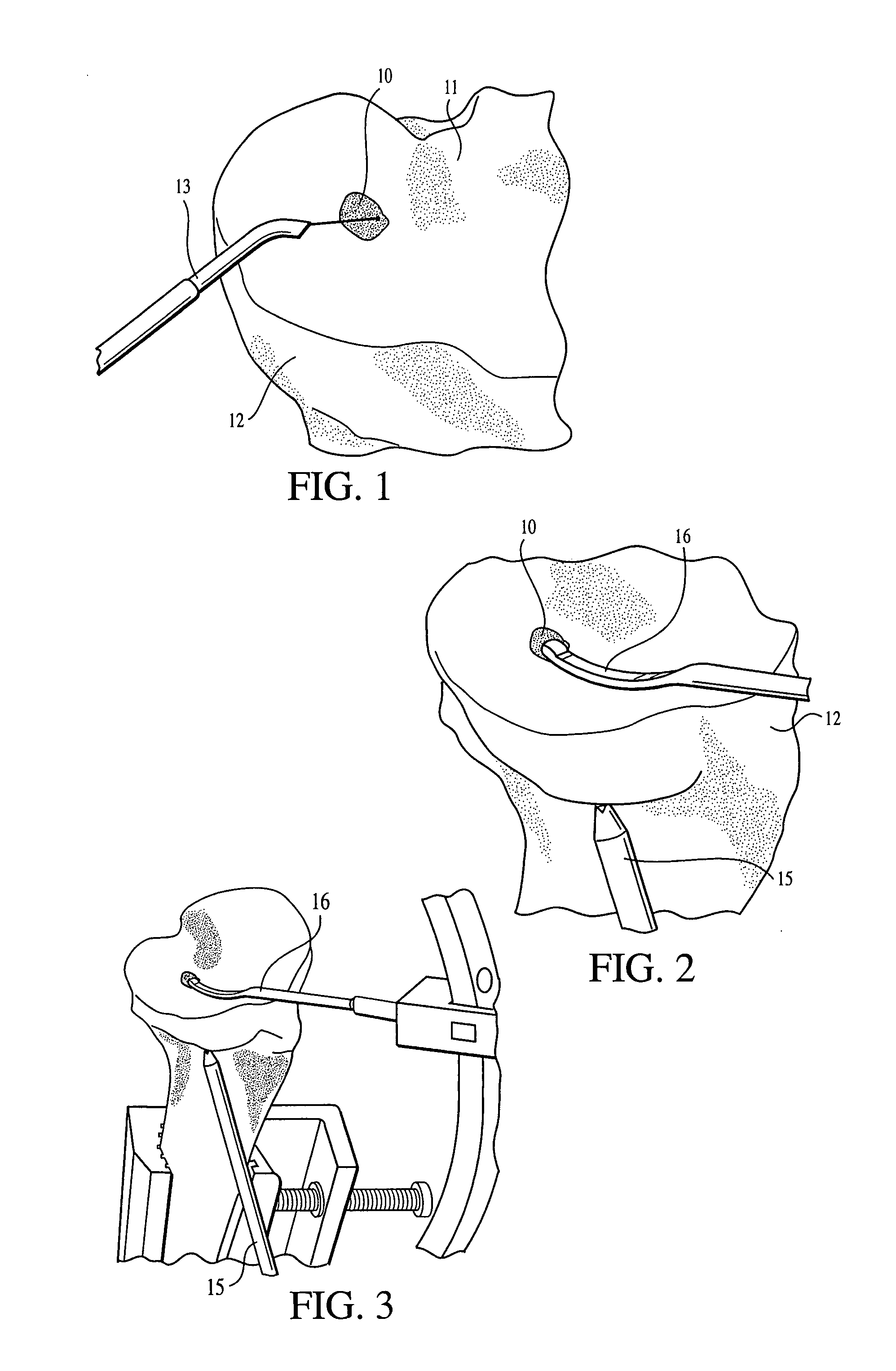
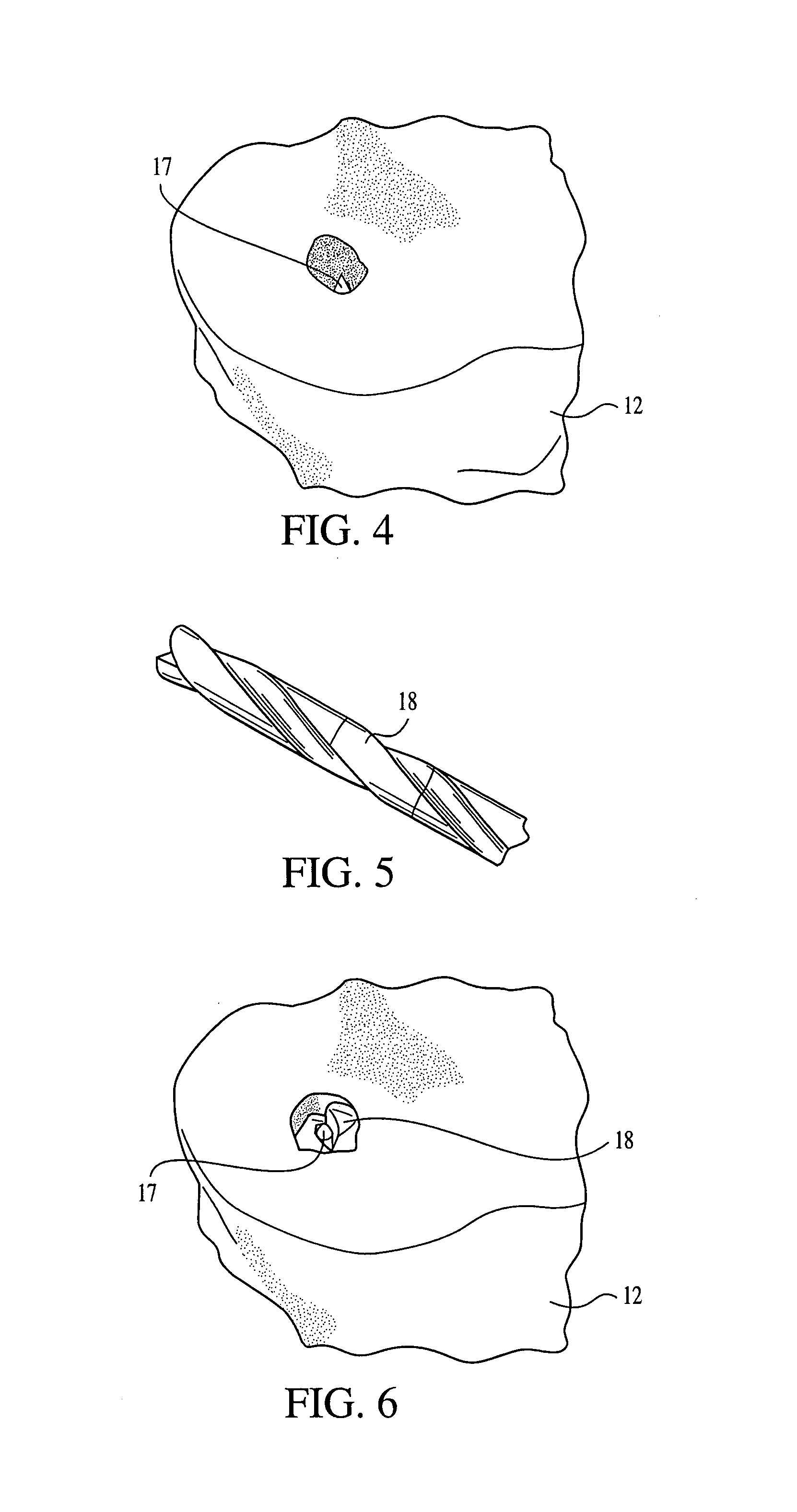
[0035]Referring now to the drawings, where like elements are designated by like reference numerals, FIG. 1 depicts osteochondral lesion 10 located on tibial surface 11 of tibia 12. The osteochondral lesion 10 is a tibial plateau lesion of about 10 mm in diameter, as measured with measurement probe 13 (FIG. 1). As described below, the osteochondral lesion 10 is drilled out to create a recipient site for an angled harvested core 50 (FIGS. 15-16) grafted in accordanc...


PUM


Abstract

A retrograde osteochondral autograft transfer system that ensures that grafted healthy bone is implanted into the recipient site in a retrograde manner as opposed to a conventional anterior manner, so that the grafted healthy bone is flush with the bone surface of the recipient size. The retrograde osteochondral autograft transfer system of the present invention employs two identically-sized harvesters which are aligned with each other for transfer and reversal of a harvested osteochondral core, such that the core can be introduced into the recipient site through a tunnel leading to the recipient site, with an articular surface of the core advanced in a leading position.

Description


Claims


Application Information

Patent Timeline
Owner ARTHREX
Why Eureka
Try Eureka