Safety of nailing device

a nailing device and safety technology, applied in the direction of nailing tools, stapling tools, manufacturing tools, etc., can solve the problem that the nailing plate cannot be moved to the ready-to-strike position, and achieve the effect of ensuring the safety of the operation of the nailing device during regular us

Inactive Publication Date: 2009-09-29
JANN YEI IND
View PDF17 Cites 9 Cited by
  • Summary
  • Abstract
  • Description
  • Claims
  • Application Information

AI Technical Summary

Benefits of technology

[0010]The primary purpose of the present invention is to provide a safety for a nailing device that eliminates inadvertent percussion of the nailing device to secure the operation safety of the nailing device.
[0013]With such an arrangement, the safety of the present invention comprises a retainer that effectively prevents the striker plate to be moved to the ready-to-strike position until the release plate is forced back into the housing. Thus, unless the nailing device is properly set on the surface of a work piece, which forces the release plate back into the housing of the nailing device, the striker plate cannot be moved to the ready-to-strike position. In this way, operation safety of the nailing device during regular uses can be secured.

Problems solved by technology

Thus, unless the nailing device is properly set on the surface of a work piece, which forces the release plate back into the housing of the nailing device, the striker plate cannot be moved to the ready-to-strike position.

Method used


Image

  • Safety of nailing device
  • Safety of nailing device
  • Safety of nailing device

Examples


Embodiment Construction

[0023]The following descriptions are of exemplary embodiments only, and are not intended to limit the scope, applicability or configuration of the invention in any way. Rather, the following description provides a convenient illustration for implementing exemplary embodiments of the invention. Various changes to the described embodiments may be made in the function and arrangement of the elements described without departing from the scope of the invention as set forth in the appended claims.

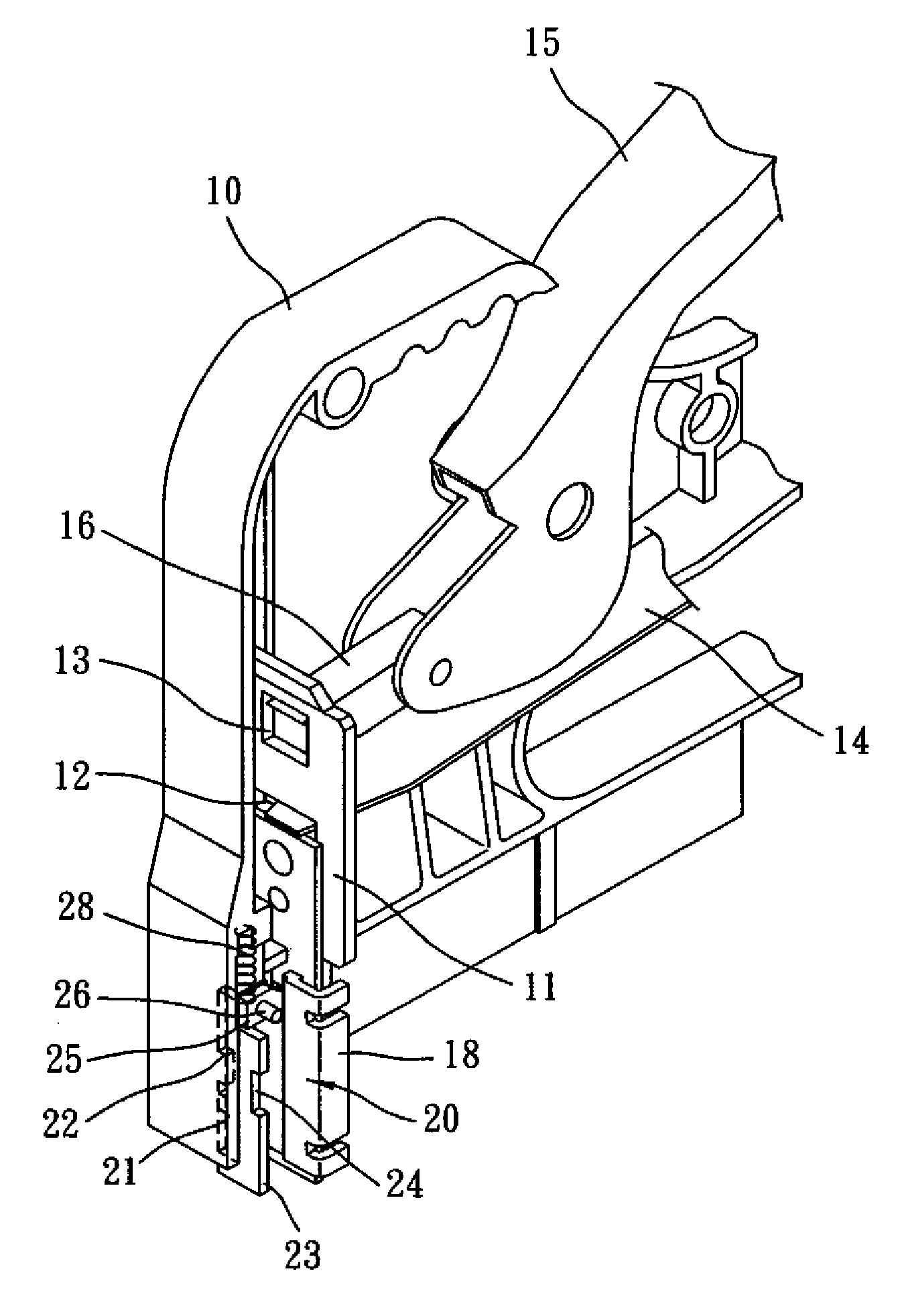
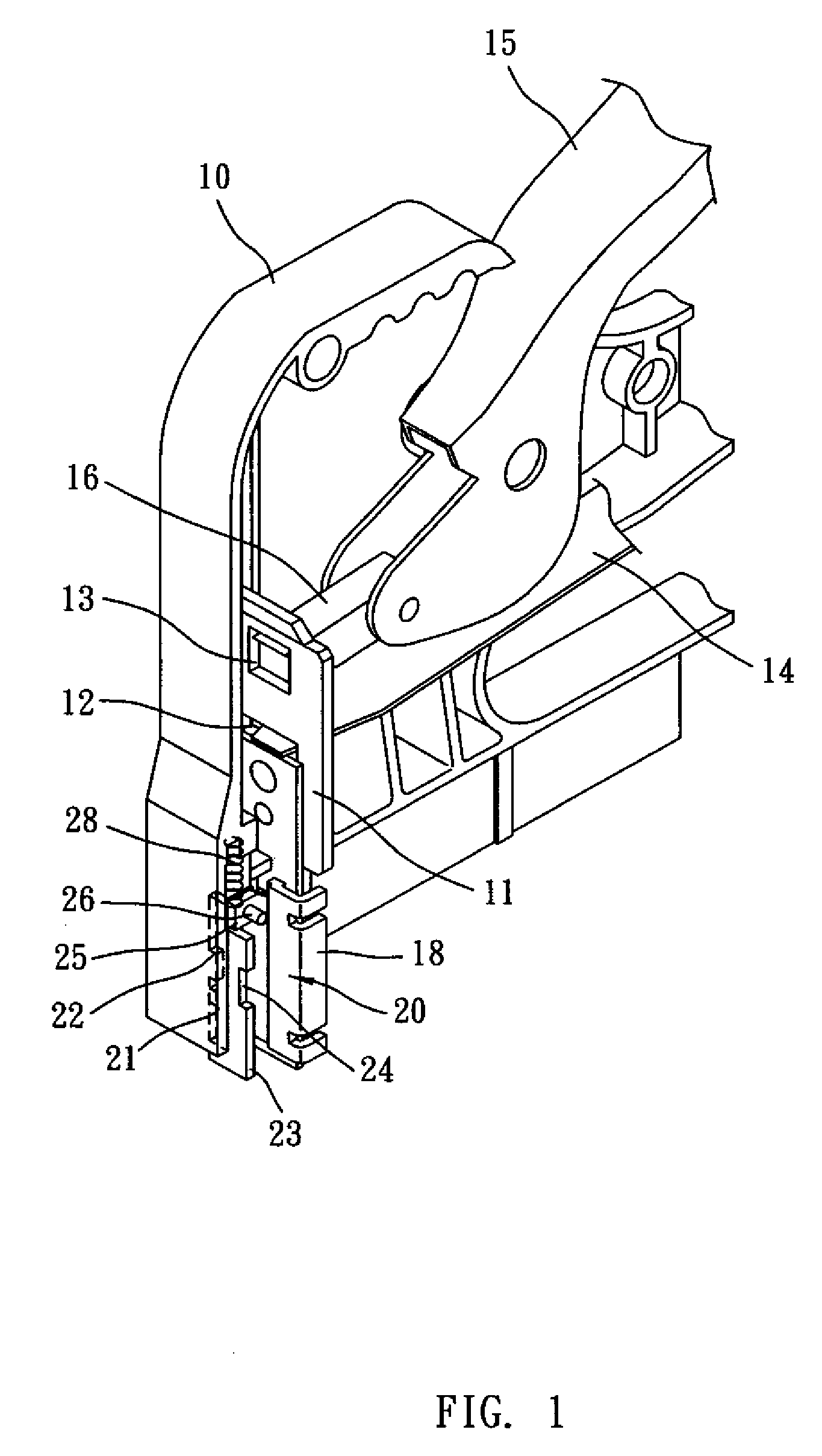
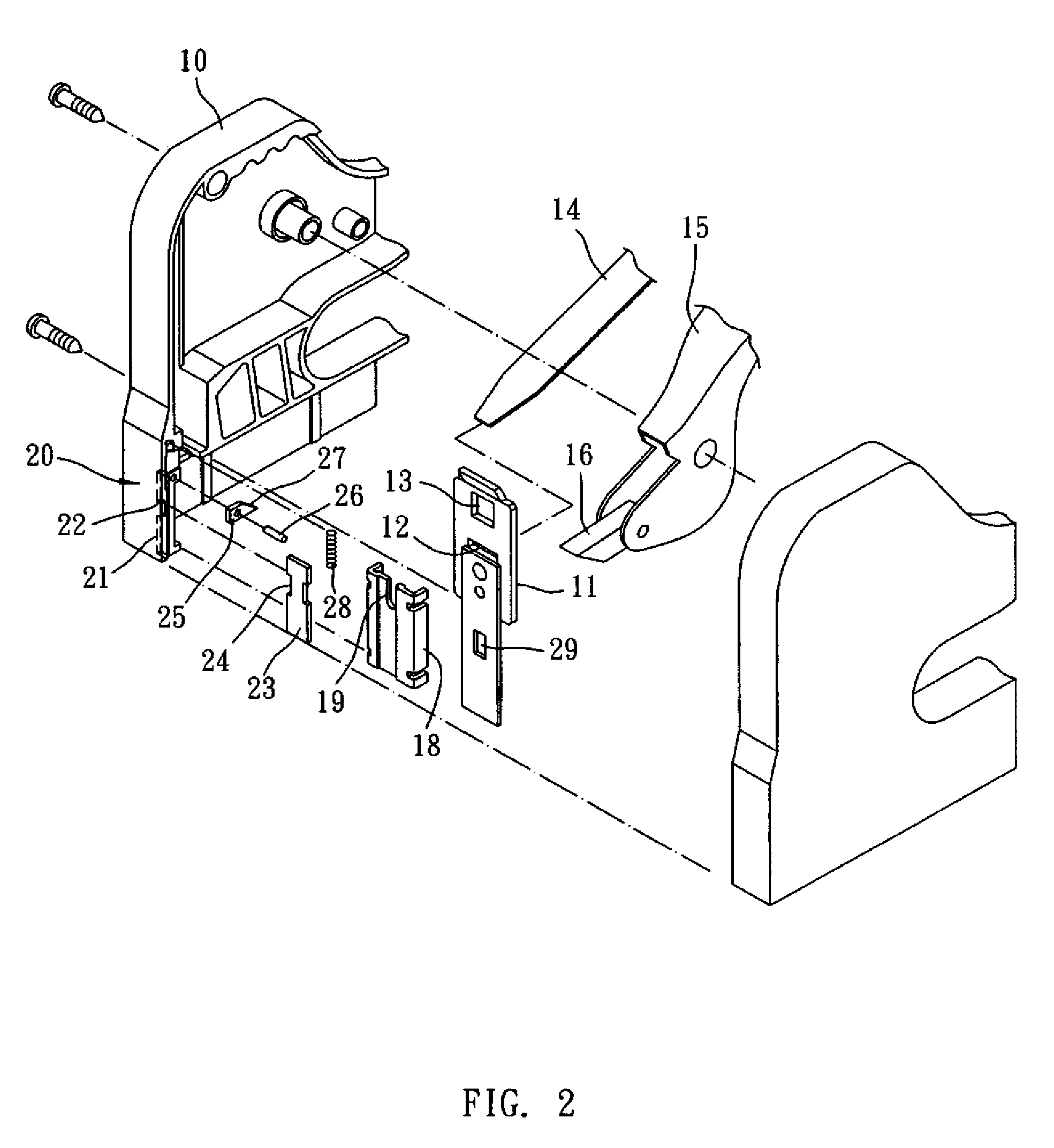
[0024]With reference to the drawings, and in particular to FIGS. 1 and 2, a safety is provided for preventing a nailing device from being accidentally triggered to shoot a nail in an unexpected manner. As shown in the drawings, the nailing device in which the safety in accordance with the present invention is embodied comprises a housing 10, a nail striker plate 11 arranged in a front end portion of the housing 10, a spring plate 14 that provides a sufficient biasing force to the striker plate 11...


PUM

PropertyMeasurementUnit
forceaaaaaaaaaa
timeaaaaaaaaaa
biasing torqueaaaaaaaaaa

Abstract

A safety is incorporated in a nailing device, which ensures operation safety of the nailing device. The nailing device includes a housing in which a striker plate is mounted and movable to a ready-to-strike position for subsequently striking a nail out of the housing. The safety includes a retainer pivoted to the housing with an inner end engaging the striker plate to retain the striker plate against movement to the ready-to-strike position and an opposite outer end engaging a release plate that is biased by a spring to partially projecting beyond the housing. When the nailing device is properly set on a work piece, the release plate is forced against the biasing spring back into the housing and the inner end of the retainer is caused to disengage from and thus freeing the striker plate.

Description

BACKGROUND OF THE INVENTION[0001](a) Technical Field of the Invention[0002]The present invention relates to a safety for nailing devices, and in particular to a safety that, unless released, prevents the nailing device from operation by blocking a nail striker plate, in order to ensure operation safety of the nailing device.[0003](b) Description of the Prior Art[0004]A nailing device functions to repeatedly and forcibly feed out nails for fixing different parts or articles together. A regular nailing device comprises a nail striker plate that is arranged inside a housing and movable up and down in a given direction. A strip of nails is accommodated in a bottom portion of the housing and is fed forward by a nail forwarding unit to locate below the striker plate for being struck out of the housing. The striker plate is movable either manually, electrically or pneumatically to a lifted, ready-to-strike position from which the striker plate is release to spontaneously strike out the nai...

Claims


Application Information

Patent Timeline
Patent Type & Authority Patents(United States)
IPC IPC(8): B27F7/00B25C5/10
CPCB25C5/10B25C1/008
Inventor CHEN, TON-YILEE, YUAN-SHUN
Owner JANN YEI IND
Why Eureka
Try Eureka