Rotary connector

a technology of rotary connectors and connectors, applied in the direction of connections, basic electric elements, electric devices, etc., can solve the problems of abnormal noise generated by sliding portions, and achieve the effect of comparatively small rotational speed

Active Publication Date: 2009-09-29
ALPS ALPINE CO LTD
View PDF9 Cites 6 Cited by
  • Summary
  • Abstract
  • Description
  • Claims
  • Application Information

AI Technical Summary

Benefits of technology

[0012]In the rotatable connector constructed in this way, the erected portion provided at the inner edge of the bottom plate of the stator housing is sandwiched between the inner tubular body and the annular flange, in the vicinity of the center of rotation where any deformation such as warpage caused by the influence of thermal expansion during resin molding, at high temperature, or the like or any positional deviation during rotation is little, and rotational speed are comparatively small. Therefore, axial movement of the rotor housing with respect to the stator housing can be suppressed. Further, since the erected portion becomes a sliding surface of the tubular portion of the lower rotor, radial movement of the rotor housing with respect to the stator housing can be suppressed, and consequently, generation of abnormal noises from a sliding portion between the stator housing and the rotor housing can be suppressed.

Problems solved by technology

As a result, there is a problem in that abnormal noises are generated from a sliding portion.

Method used


Image

  • Rotary connector
  • Rotary connector
  • Rotary connector

Examples


Embodiment Construction

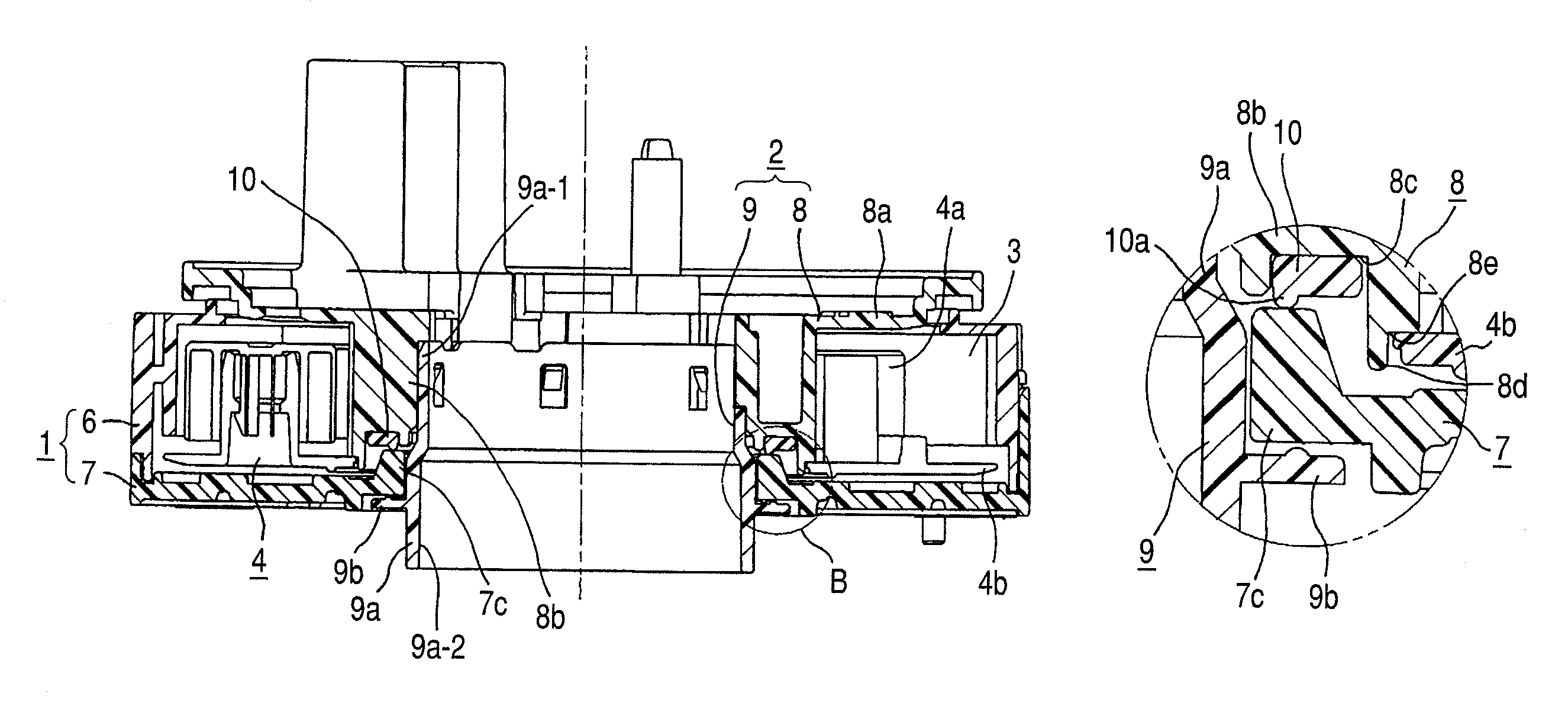
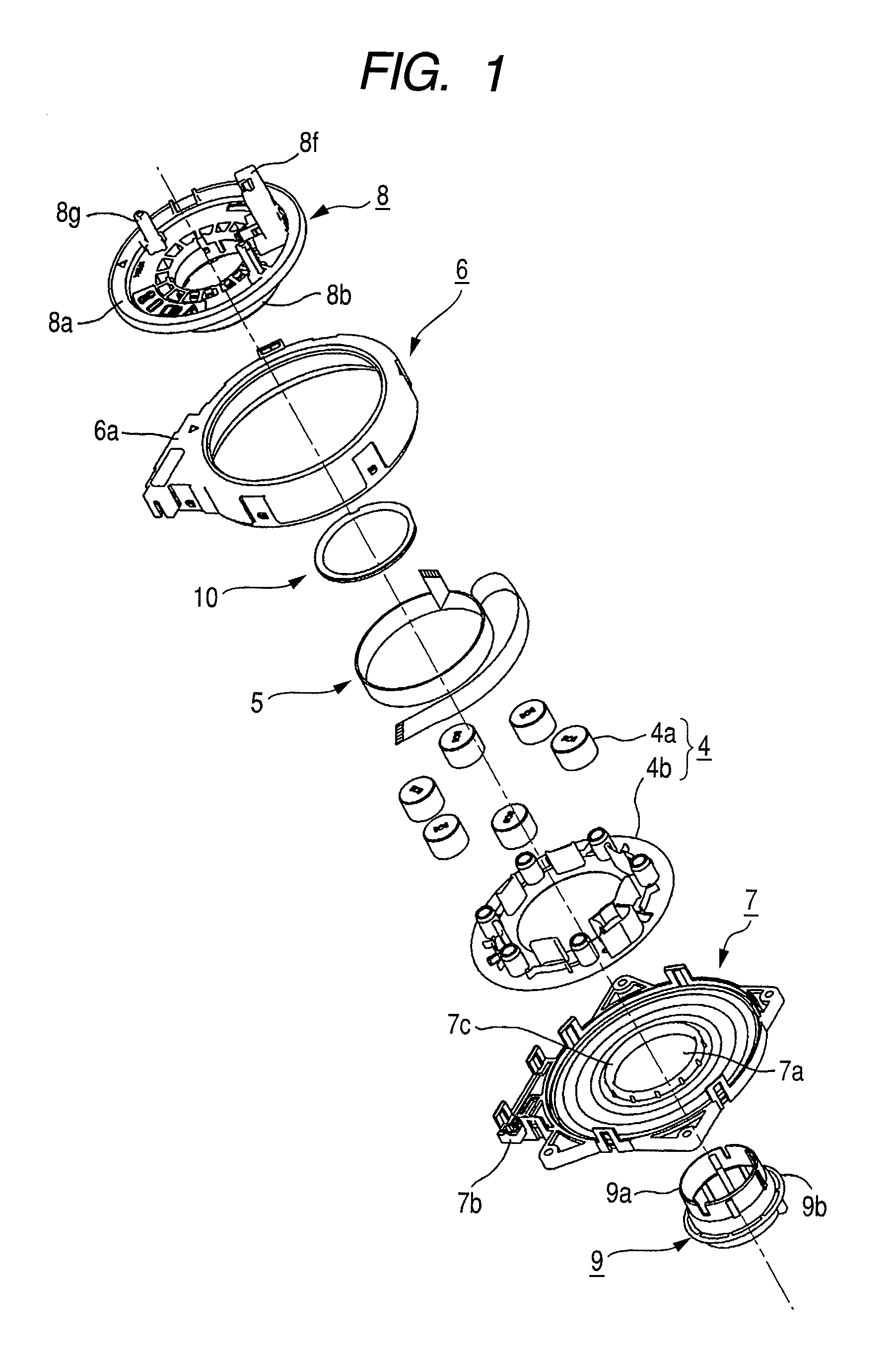
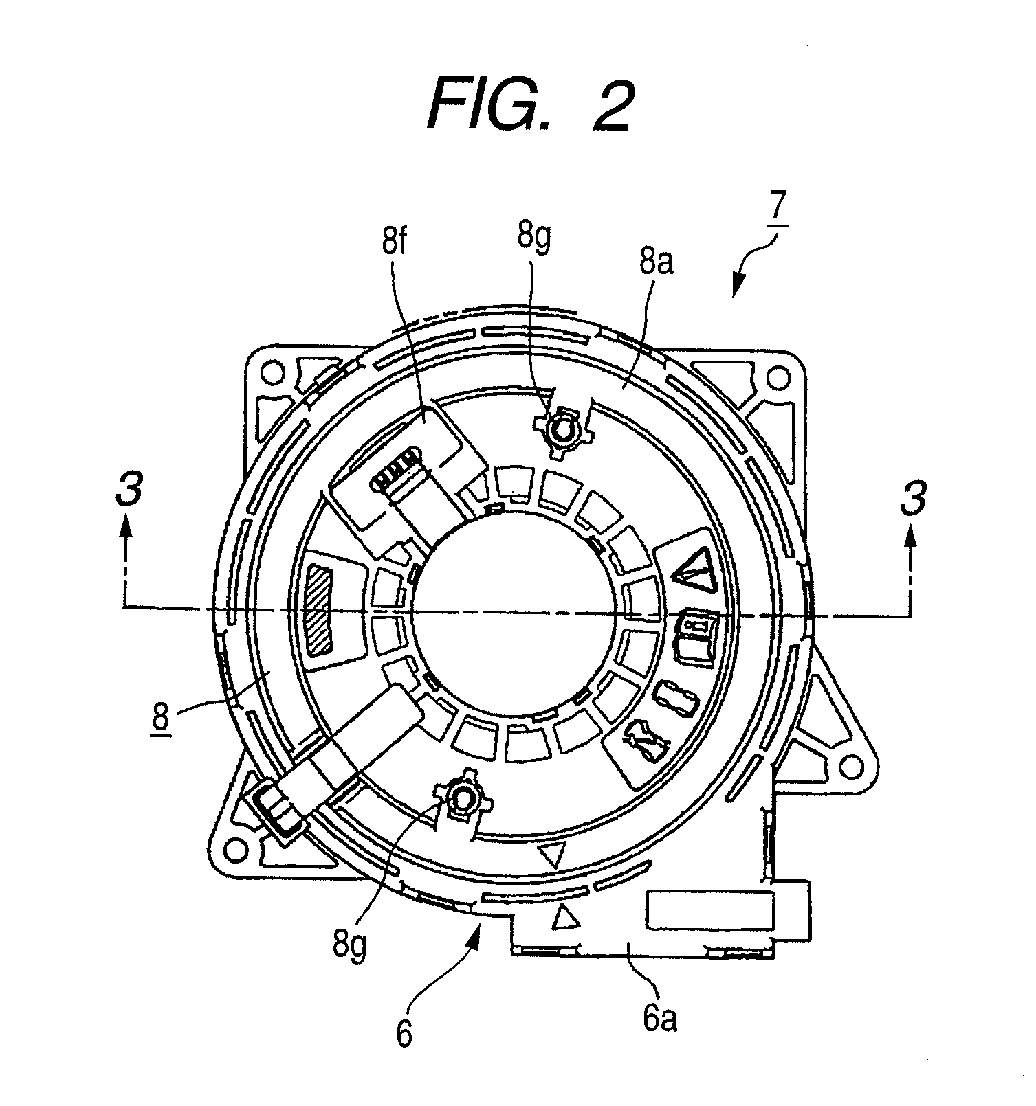
[0021]Now, an embodiment of the invention will be described with reference to the drawings in which FIG. 1 is an exploded perspective view of a rotary connector according to an embodiment of the invention, FIG. 2 is a top view of the rotary connector of FIG. 1, FIG. 3 is a sectional view taken along a line A-A of FIG. 2, FIG. 4 is an enlarged view of a portion B of FIG. 3, FIG. 5 is a perspective view showing the shape of a bottom face of a ring member used for the rotary connector of FIG. 1, FIG. 6 is a bottom view of the ring member of FIG. 5, and FIG. 7 is a side view of the ring member of FIG. 5.

[0022]The rotary connector according to this embodiment generally includes a stator housing 1, a rotor housing 2 rotatably mounted on the stator housing 1, a movable body 4 rotatably arranged within an annular housing space 3 formed between the housings 1 and 2, and a beltlike flat cable (flexible cable) 5 housed within the housing space 3 so as to be able to be wound and rewound.

[0023]T...


PUM


Abstract

A rotary connector includes a stator housing in which an outer tubular body is erected at an outer edge of a bottom plate having a center hole, an upper rotor having a top plate facing the bottom plate and an inner tubular body facing the outer tubular body, and rotatably mounted on the stator housing, a lower rotor having a tubular portion inserted through the center hole towards the top plate from the bottom plate and fixed to the inner tubular body, and an annular flange protruding radially outward from the tubular portion and faces the bottom plate, and a flexible cable housed within an annular housing space formed between the stator housing and the upper rotor so as to be able to be wound and rewound, and having one end attached to the stator housing and the other end attached to the rotor. An inner edge of the bottom plate is provided with an erected portion erected in an axial direction, and the erected portion is made to face the tubular portion such that an inner peripheral surface of the erected portion becomes a sliding surface of the tubular portion, and the erected portion is arranged between a bottom of the inner tubular body and the annular flange such that axial movement of the upper rotor and the lower rotor is suppressed by the erected portion.

Description

CLAIM OF PRIORITY[0001]The present application claims the benefit of and contains subject matter related to Japanese Patent Application Japanese Patent Application No. 2007-325045 filed in the Japanese Patent Office on Dec. 17, 2007, the entire contents which is hereby incorporated herein by reference.BACKGROUND[0002]1. Technical Field[0003]The present invention relates to a rotary connector in which a stator housing and a rotor housing which are rotatably combined are electrically connected by a flexible cable, and particularly, to a rotary connector in which a rotor housing is constructed by an upper rotor and a lower rotor which are connected by snapping, etc.[0004]2. Related Art[0005]A rotary connector includes a stator housing fixed to an assembly of a combination switch, which is provided in a steering system of an automobile, or the like, a rotor housing attached to a steering wheel, a flexible cable housed within an annular housing space formed between these housings, and th...

Claims


Application Information

Patent Timeline
Patent Type & Authority Patents(United States)
IPC IPC(8): H01R35/04
CPCH01R35/025
Inventor ARAKI, SHUNJITAKAHASHI, YASUNORI
Owner ALPS ALPINE CO LTD
Why Eureka
Try Eureka