Power transfer device

a power transfer device and power transfer technology, applied in the direction of control devices, driver input parameters, compacts, etc., can solve the problems of so-called stick-slip phenomenon, vibration of the driveline of the main drive wheel side, etc., to suppress abnormal noise, reduce the fastening force, and suppress the vibration of the main drive side output shaft

Active Publication Date: 2012-04-17
SUBARU CORP
View PDF11 Cites 5 Cited by
  • Summary
  • Abstract
  • Description
  • Claims
  • Application Information

AI Technical Summary

Benefits of technology

[0006]The object of the present invention is to suppress vibration in the driveline of the main drive wheel that occurs when a vehicle is turning, as well as suppress abnormal noise that is generated from the transmission system.
[0012]The present invention comprises a main drive side output shaft that is linked to a transmission system, an auxiliary drive side output shaft that is linked to a transmission system via a friction clutch mechanism, and a clutch control means that decreases the fastening force of the friction clutch mechanism based on the vibration state of main drive side output shaft, so it is possible to suppress vibration of the main drive side output shaft, as well as suppress abnormal noise that is generated from the transmission system.

Problems solved by technology

However, when attempting to control the friction clutch mechanism in the slip state, microscopic fastening and release of the friction plate is repeated, and there is a possibility that the so-called stick-slip phenomenon may occur.
This kind of stick-slip phenomenon becomes the cause of vibration of the driveline on the auxiliary drive wheel side that has a small inertia force, and in a condition where the transmission state of the drive torque in the transmission becomes neutral, not only does this phenomenon cause vibration in the driveline of the auxiliary drive wheel side, but also causes vibration of the driveline of the main drive wheel side.

Method used


Image

  • Power transfer device
  • Power transfer device
  • Power transfer device

Examples


Embodiment Construction

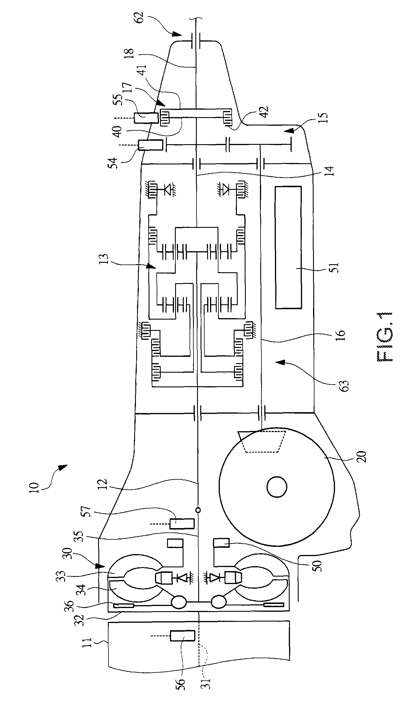
[0020]The preferred embodiments of the invention will be explained below with reference to the accompanying drawings. FIG. 1 is a skeleton drawing of an automatic transmission 10 of a four-wheel drive vehicle that comprises a power transfer device of an embodiment of the present invention. As shown in FIG. 1, the automatic transmission 10 comprises: a transmission input shaft 12 that is linked to the engine 11, which is the drive source; and a transmission output shaft 14 that is linked to the input shaft 12 via a transmission system 13. A front wheel output shaft 16, which is the output shaft of the main drive side, is linked to the transmission output shaft 14 via a gear train 15, and a rear wheel output shaft 18, which is the output shaft of the auxiliary drive side, is linked to the transmission output shaft 14 via a transfer clutch 17 (friction clutch mechanism, hydraulic clutch mechanism).

[0021]The drive force that is output from the transmission system 13 is transmitted from ...


PUM


Abstract

The object of the present invention is to suppress the generation of abnormal noise from a transmission system that occurs when a vehicle is turning. A front wheel output shaft is directly linked with the transmission system, and a rear wheel output shaft is linked to the transmission system via a transfer clutch. When the front wheel output shaft rpm Nf and the rear wheel output shaft rpm Nr separate from each other beyond a specified value (α2) while turning a corner, and then the accelerator pedal is released and the engine rpm Ne and turbine rpm Nt approach each other beyond a specified value (β2), and then if vibration at a specified vibration frequency appears in the front wheel output shaft rpm Nf (γ2), the duty ratio Rd of the clutch pressure control valve 52 is decreased (δ2). Next, as the duty ratio Rd decreases, when it is determined that vibration in the front wheel output shaft rpm Nf has been eliminated (ε2), normal slip control is restored, and control is performed so that the duty ratio Rd is increased again (ζ2). By doing this, it is possible to suppress vibration of the front wheel output shaft, and thus suppress the generation of abnormal noise from the transmission system.

Description

CROSS REFERENCE TO RELATED APPLICATIONS[0001]This application claims priority under 35 U.S.C. 119 based upon Japanese Patent Application Serial No. 2008-056559, filed on Mar. 6, 2008. The entire disclosure of the aforesaid application is incorporated herein by reference.FIELD OF THE INVENTION[0002]The present invention relates to a power transfer device that distributes a driving force to main drive wheels and auxiliary drive wheels via a friction clutch mechanism.BACKGROUND OF THE INVENTION[0003]As a four-wheel drive vehicle that drives the front and rear wheels, there is a vehicle that varies the torque-distribution ratio of the front and rear wheels according to the driving conditions. This kind of four-wheel drive vehicle comprises: main drive wheels, which are on one of the front wheel side and the rear wheel side, to which the drive torque is directly transmitted from the transmission system; and auxiliary drive wheels, which are on the other one of the front wheel side and th...

Claims


Application Information

Patent Timeline
Patent Type & Authority Patents(United States)
IPC IPC(8): B60W10/00B60K17/344
CPCB60K17/35B60K23/0808B60W2510/104B60W2540/103F16D2500/10431Y10T477/753F16D2500/3144F16D2500/50293F16D2500/508F16D2500/70426Y10T477/6418F16D2500/31B60W2540/18
Inventor SAITO, TOMOHIRO
Owner SUBARU CORP
Why Eureka
Try Eureka