Gas compressor

A technology of gas compressors and cylinder blocks, which is applied in liquid fuel engines, mechanical equipment, machines/engines, etc., and can solve the problems of large-scale and weight gas compressors

Inactive Publication Date: 2011-10-12
CALSONIC KANSEI CORP
View PDF5 Cites 6 Cited by
  • Summary
  • Abstract
  • Description
  • Claims
  • Application Information

AI Technical Summary

Problems solved by technology

In this case, there will be a problem of increasing the size and weight of the gas compressor

Method used


Image

  • Gas compressor
  • Gas compressor
  • Gas compressor

Examples


Embodiment Construction

[0017] Hereinafter, an embodiment of the present invention will be described with reference to the drawings.

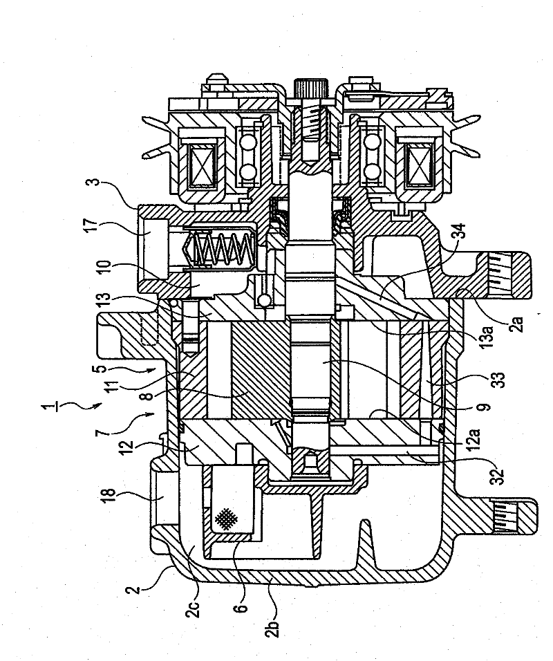
[0018] The gas compressor 1 of this embodiment is a vane rotary compressor. like figure 1 As shown, the gas compressor 1 has a housing 2 and a compression mechanism 5 .

[0019] The housing 2 has a bottomed cylindrical shape whose rear end is closed by a bottom wall 2b. The compression mechanism 5 and the gas-liquid separation unit 6 are accommodated in the housing portion 2c inside the casing 2 . A discharge port 18 for the refrigerant is formed on the upper portion of the casing 2 . An opening 2 a is formed at the front end of the housing 2 . On the side of the opening 2a of the housing 2, a front cylinder head (head) 3 is fixed. On the front cylinder head 3, a suction port 17 for sucking refrigerant into the compression mechanism 5 is formed. The suction port 17 communicates with the suction chamber 10, and the suction chamber 10 communicates with the suctio...


PUM


Abstract

A gas compressor provided with a cylinder block, a rear side block, a front side block, a cylinder chamber formed by the three blocks, a rotor rotatably provided in the cylinder chamber, vane grooves formed in the rotor, vanes inserted in the vane grooves, and a suction hole provided in either the front side block and / or the rear side block. A refrigerant is sucked into the cylinder chamber from the suction hole. The edge of the opening of the suction hole is composed of an in-chamber opening edge located within the cylinder chamber and of an in-block opening edge facing the side wall of the cylinder block. The in-chamber opening edge is located on the elliptic inner wall side from the outer periphery of the rotor. The configuration suppresses the tilt of the vanes and also suppresses cut damage and wear of the blocks, vibration, and noise.

Description

technical field [0001] The present invention relates to a rotary vane gas compressor used in a vehicle air conditioner and the like. Background technique [0002] In the vane rotary gas compressor, a cylinder chamber is formed by a cylinder block, a rear cylinder and a front cylinder arranged on both sides of the cylinder block. Furthermore, a rotatable rotor is accommodated in the cylinder chamber. The interior of the cylinder chamber is surrounded by an elliptical inner wall. The vanes inserted into the vane grooves of the rotor partition the inside of the cylinder chamber to form a plurality of compression chambers. The suction hole formed in the front block communicates with the cylinder chamber. The refrigerant is sucked into the cylinder chamber through the suction hole. The sucked refrigerant is compressed by the blades along with the rotation of the rotor, and then the refrigerant is discharged to the refrigeration cycle system (for example, refer to Japanese Pat...

Claims


Application Information

Patent Timeline
Patent Type & Authority Applications(China)
IPC IPC(8): F04C18/344F04C29/12
CPCF04C18/3446F04C29/12F04C2250/101F04C2270/12F04C2270/13
Inventor 饭岛博史
Owner CALSONIC KANSEI CORP
Why Eureka
Try Eureka