Flow path selector valve

A switching valve, flow channel technology, applied in the field of flow channel switching valve, to achieve the effect of shortening the switching time, reliable switching, and reducing friction

Inactive Publication Date: 2011-05-04
SAGINOMIYA SEISAKUSHO INC
View PDF1 Cites 6 Cited by
  • Summary
  • Abstract
  • Description
  • Claims
  • Application Information

AI Technical Summary

Problems solved by technology

[0004] However, in the technique of Patent Document 1, the state in which the main valve is lifted from the valve seat is the state in which the main valve operates smoothly
In addition, in order to switch from the state where the pressure equalizing hole is "open" and the communication hole is "closed" to the state where the pressure equalizing hole is "closed" and the communication hole is "open", it is necessary to reverse the motor by a predetermined angle, and the main valve also has Possibility of movement, there is still room for improvement
In addition, the closing valve that opens and closes the pressure equalizing hole and the communication hole is in a free state relative to the main valve, so there is still room for improvement in the sealing performance of the pressure equalizing hole and the communication hole

Method used


Image

  • Flow path selector valve
  • Flow path selector valve
  • Flow path selector valve

Examples


Embodiment Construction

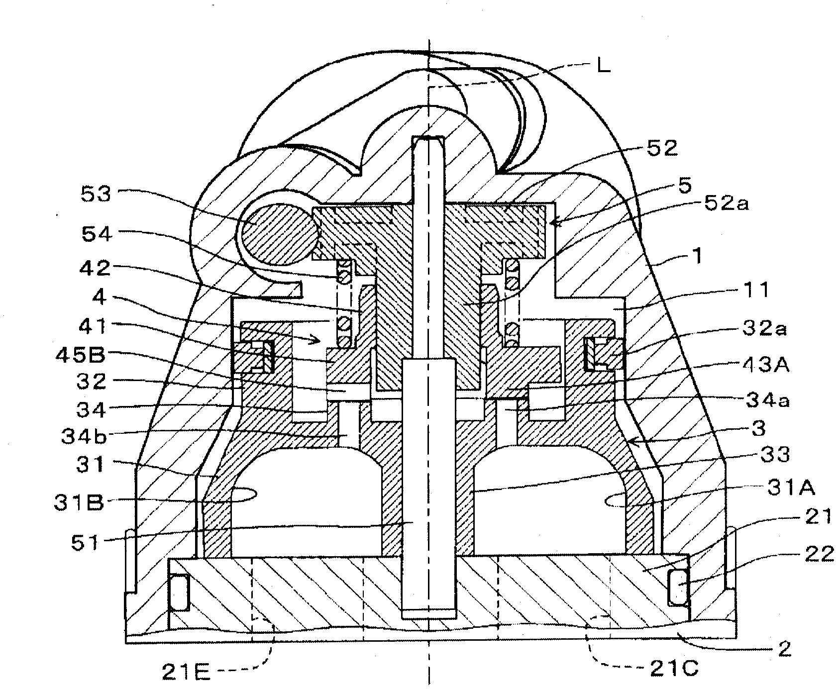
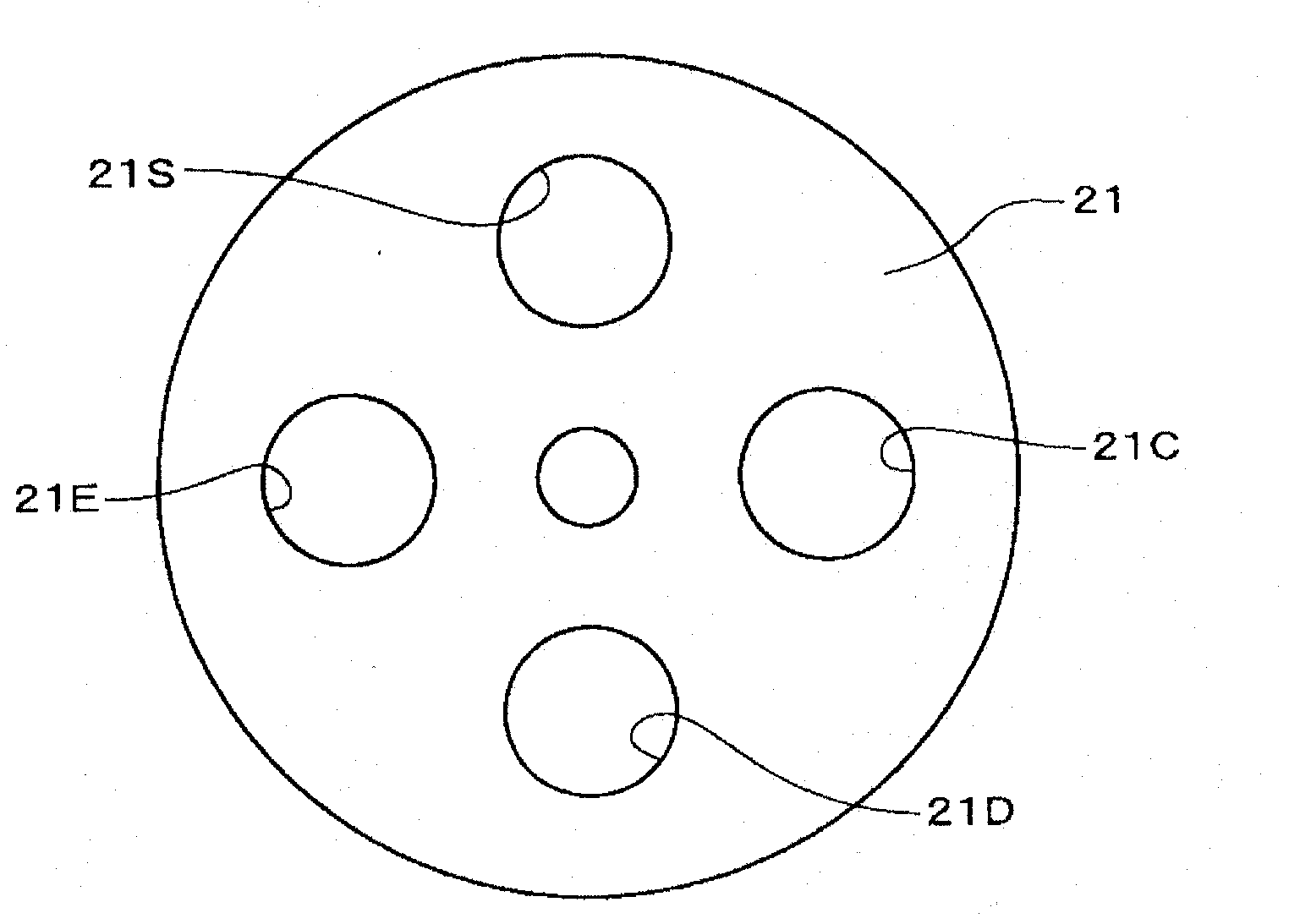
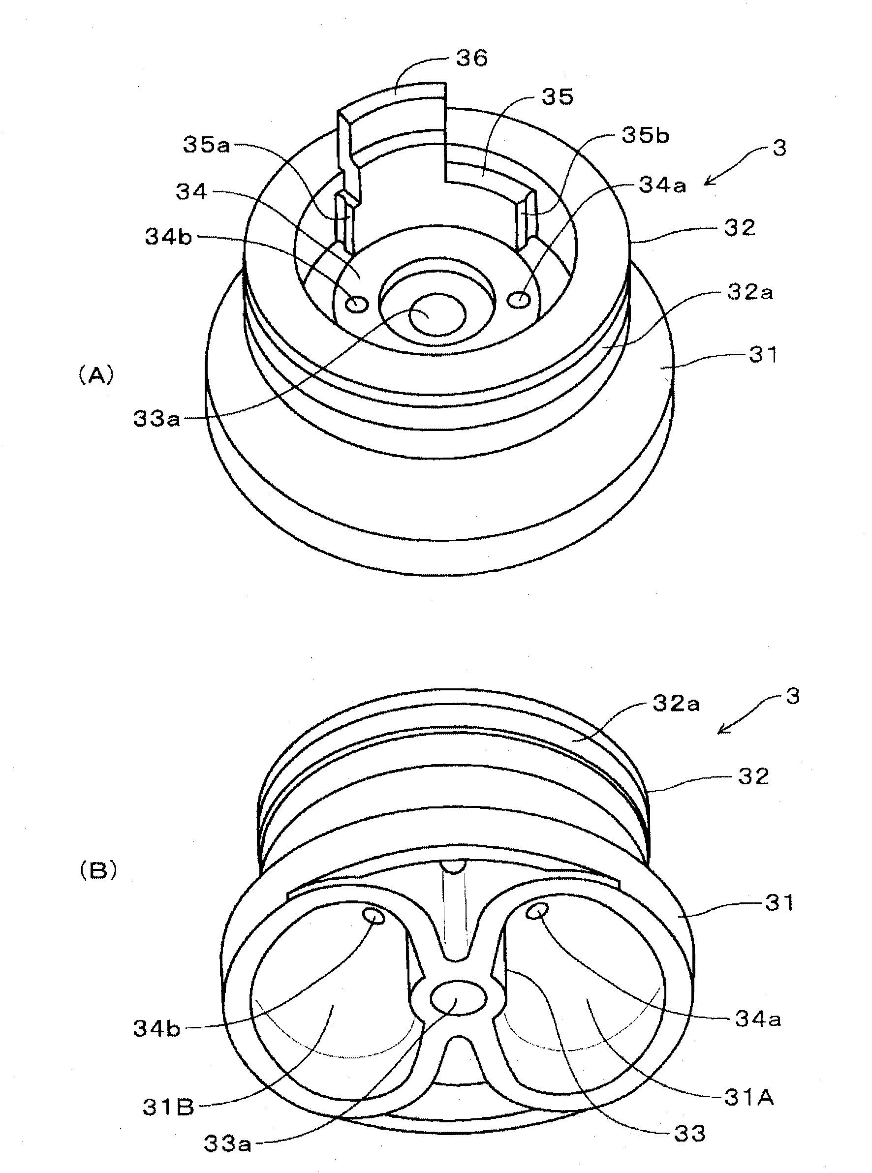
[0035] Next, embodiments of the channel switching valve of the present invention will be described with reference to the drawings. figure 1 It is a longitudinal sectional view of the channel switching valve according to the first embodiment of the present invention, figure 2 is a top view of the valve seat of the channel switching valve, image 3 is a perspective view of the main valve of the channel switching valve, Figure 4 is a perspective view of the auxiliary valve of the channel switching valve, Figure 5 ~ Figure 7 This is an explanatory diagram of the operation of the channel switching valve. and also, figure 1 It is a figure showing the middle of switching of the main valve.

[0036] The channel switching valve of the first embodiment has a case member 1 and a valve seat member 2 . A valve chamber 11 cut into a substantially cylindrical shape is formed in the housing member 1 . In addition, a circular platform-shaped valve seat 21 is formed on the valve seat m...


PUM


Abstract

A flow path selector valve for switching between a cooling state and a heating state by rotation of a main valve (3) together with a auxiliary valve (4), wherein rotational operation of the main valve (3) and the auxiliary valve (4) are simplified to make operation of the main valve (3) reliable and to reduce a switching time. An outdoor heat exchanger-side communication passage (31A) and an indoor heat exchanger-side communication passage (31B) are formed in the main valve (3). An outdoor heat exchanger-side equalizing hole (34a) for connecting the outdoor heat exchanger-side communication passage (31A) to a valve chamber (11) is formed in the main valve. An indoor heat exchanger-side equalizing hole (34b) for connecting the indoor heat exchanger-side communication passage (31B) to the valve chamber (11) is formed in the main valve (3). A closing section (43A) for closing the outdoor heat exchanger-side equalizing hole (34a) and an equalizing hole opening section (45B) for opening the indoor heat exchanger-side communication passage (34b) are also formed in the auxiliary valve (4). A closing section for closing the indoor heat exchanger-side equalizing hole (34b) and an equalizing hole opening section for opening the outdoor heat exchanger-side communication passage (34a) are also formed in the auxiliary valve. A support section sliding on an auxiliary valve seat (34) is formed on the auxiliary valve (4). The main valve (3) is rotated 90 DEG by merely operating the auxiliary valve (4) in either forward or reverse directions, and this switches between the cooling state and the heating state.

Description

technical field [0001] The present invention relates to a channel switching valve used in heat pump refrigeration cycle systems and the like to switch refrigerant channels. Background technique [0002] Conventionally, there is a technique disclosed in Patent No. 4081290 (Patent Document 1) as such a channel switching valve (four-way switching valve). In the technique of Patent Document 1, when switching from cooling to heating or from heating to cooling, the support shaft supporting the main valve is rotated, the closing valve support is rotated on the main valve by the driving part, and the closing valve is passed through the main valve. The rotation of the support body opens and closes the communication hole or pressure equalization hole formed on the main valve. And, by the rotation of the support shaft, the main valve integrated with the closing valve support body is rotated on the valve seat. And, in the cooling state, the pressure equalizing hole is "closed" and the...

Claims


Application Information

Patent Timeline
Patent Type & Authority Applications(China)
IPC IPC(8): F16K11/076F16K31/04F16K31/53F25B13/00F25B41/04
CPCF16K11/0743F25B41/26Y10T137/86839Y10T137/86863
Inventor 南泽英树日下直树
Owner SAGINOMIYA SEISAKUSHO INC
Why Eureka
Try Eureka