Method and installation for the production of synthesis gas

A technology for synthesis gas and equipment, which is applied in hydrogen/syngas production, chemical instruments and methods, and joint combustion mitigation, etc., to achieve the effect of reducing costs and investment costs

Inactive Publication Date: 2009-06-03
卢吉股份有限公司
View PDF1 Cites 8 Cited by
  • Summary
  • Abstract
  • Description
  • Claims
  • Application Information

AI Technical Summary

Problems solved by technology

This can cause problems especially when the intake gas has a high content of heavy components

Method used


Image

  • Method and installation for the production of synthesis gas
  • Method and installation for the production of synthesis gas
  • Method and installation for the production of synthesis gas

Examples


Embodiment Construction

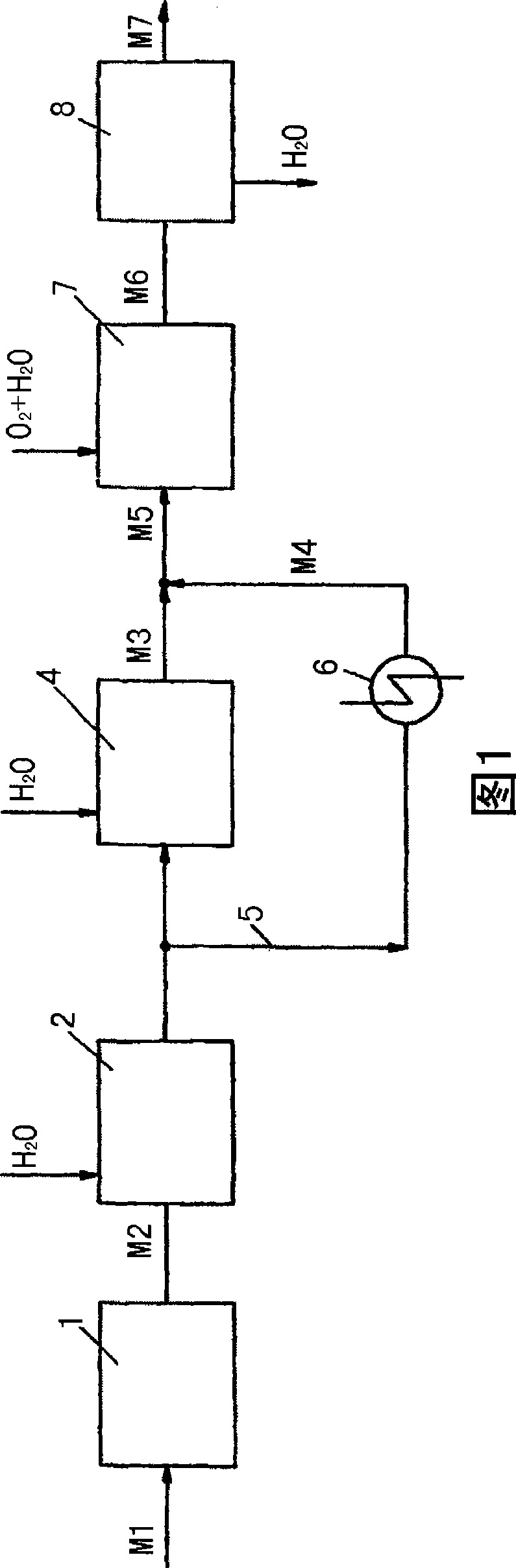
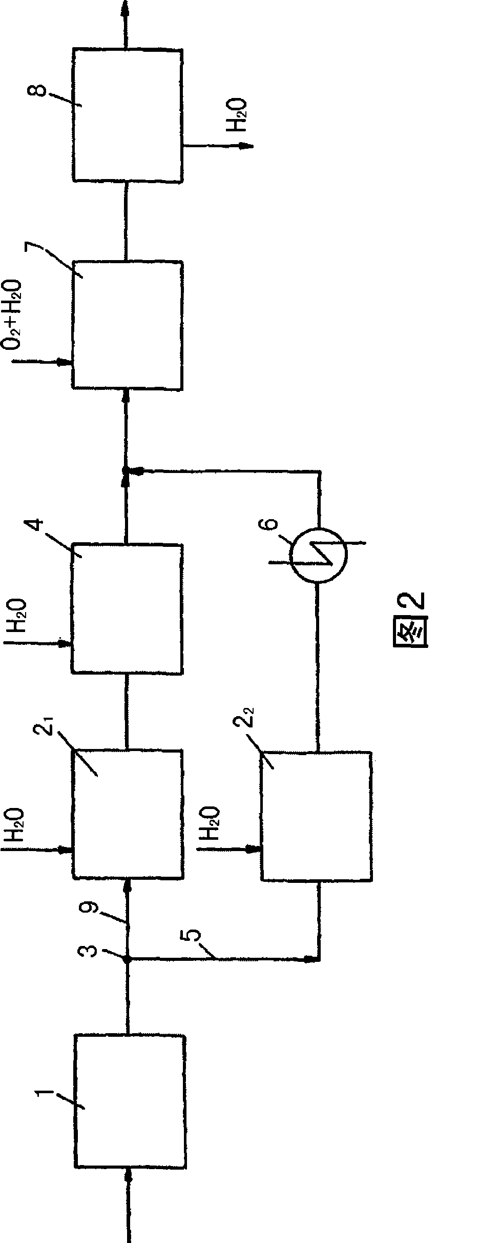
[0026] In the flow diagram of the method according to the invention for producing synthesis gas shown schematically in FIG. 1 , the raw material, in particular natural gas, is firstly freed of interfering by-products, especially sulfur, in a desulfurization plant 1 . Subsequently, natural gas (for example with a content of higher hydrocarbons greater than 12 vol.-%, ie hydrocarbons with two or more carbon and hydrogen atoms) is mixed with water or steam and introduced into the pre-reforming unit 2 middle. Here, for example, use is made of a steam reformer operated adiabatically with a nickel-based or copper-based catalyst, in which steam reforming reaction converts the carbon Hydrogen compounds are converted to C 1 compound. The selected temperature makes the reaction equilibrium largely shift to the methane side. Higher hydrocarbons will crack into CO and H 2 , followed by the main reaction to form methane. Then we get methane-rich and H-containing 2 and CO 2 gas. Acc...


PUM


Abstract

According to the invention, synthesis gas is produced from a starting material, particularly natural gas, which contains hydrocarbons, by dividing a feed flow of the starting material into a first partial flow and a second partial flow. The first partial flow is fed to a steam reformer (4) in which said partial flow, along with steam, is catalytically converted into a gas flow containing carbon oxides. The first partial flow is then recombined with the second partial flow, and the combined gas flow is fed to an autothermal reformer (7) in which the gas flow is autothermally reformed to a synthesis gas along with oxygen-rich gas in the presence of a cracking catalyst. In order to be able to process a starting material that has a high concentration of higher hydrocarbons, the entire starting material is fed to a pre-reformer (2) upstream of the steam reformer (4) and upstream of the autothermal reformer (7), higher hydrocarbons being largely eliminated from the starting material in said pre-reformer (2).

Description

technical field [0001] The invention relates to a method and a plant for the production of synthesis gas from hydrocarbon-containing raw materials, especially natural gas. Wherein the incoming stream of the raw material is divided into a first split stream and a second split stream, wherein the first split stream is directed to a steam reformer where the first split stream is catalytically converted together with water vapor into a gas containing hydrogen and carbon oxides The stream of material, after steam reforming, the first sub-stream is combined with the second sub-stream, and the combined gas stream is introduced into an autothermal reformer (autothermer reformer), where the combined The gas stream is autothermally reformed with oxygen-enriched gas into synthesis gas. Background technique [0002] In particular, natural gas is used as feedstock for the production of synthesis gas, as the synthesis gas is subsequently used for the production of other chemicals such as...

Claims


Application Information

Patent Timeline
Patent Type & Authority Applications(China)
IPC IPC(8): C01B3/38
CPCC01B2203/1241C01B2203/068Y02E20/18C01B2203/143C01B2203/061C01B2203/0244C01B3/382C01B2203/127C01B2203/141C01B2203/0233
Inventor 安德烈亚斯·博尔曼迪克·米勒
Owner 卢吉股份有限公司
Why Eureka
Try Eureka