Optical filter device, optical module and electronic apparatus
An optical filter, interference filter technology, applied in optics, measuring devices, optical components, etc., can solve the problems affecting the optical characteristics of the wave and interference filter, the tilt of the interference filter or the deflection on the substrate, etc.
- Summary
- Abstract
- Description
- Claims
- Application Information
AI Technical Summary
Problems solved by technology
Method used
Image

Examples
no. 1 approach
[0048] Hereinafter, a first embodiment according to the present invention will be described based on the drawings.
[0049] [Configuration of Optical Filter Device]
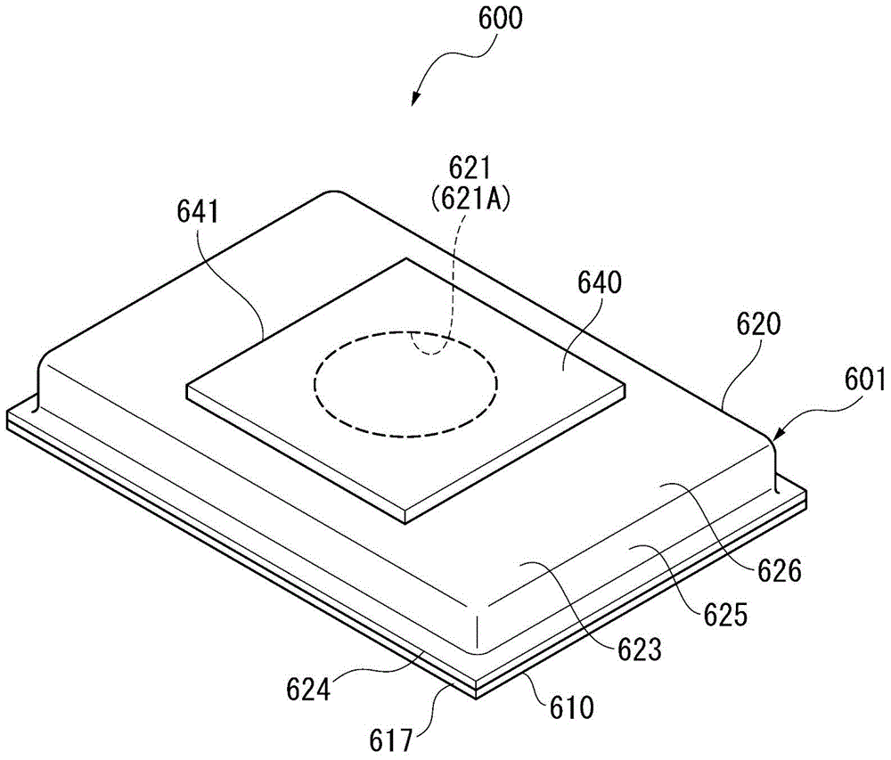
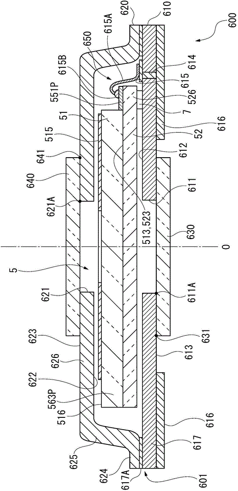
[0050] figure 1 It is a perspective view showing a schematic configuration of the optical filter device 600 according to the first embodiment of the present invention. figure 2 is a cross-sectional view showing the optical filter device 600 .
[0051] The optical filter device 600 is a device that extracts light of a predetermined target wavelength from incident light to be inspected and emits it. The optical filter device 600 includes a housing 601 and a variable wavelength interference filter 5 housed in the housing 601. (refer to figure 2 and image 3 ). Such an optical filter device 600 can be incorporated into, for example, an optical module such as a colorimetric sensor, an electronic device such as a colorimetric device, or a gas analysis device. In addition, configurations of an optical module and...
no. 2 approach
[0160] Next, a second embodiment according to the present invention will be described based on the drawings.
[0161] In this embodiment, the difference from the above-mentioned first embodiment is that the fixing members are arranged at positions overlapping with the respective electrode pads 541P, 551P, 563P, and 564P in a plan view of the filter.
[0162] Figure 7 It is a schematic diagram showing the positional relationship between the electrode pads 541P, 551P, 563P, and 564P and the fixing member 7A in plan view of the filter in the optical filter device according to the second embodiment of the present invention. In addition, it basically has the same structure as 1st Embodiment except the said difference. In the following description of the embodiments, the same reference numerals are assigned to the configurations that have already been described, and the description thereof will be omitted or simplified.
[0163] Such as Figure 7 As shown, in a plan view of the ...
no. 3 approach
[0170] Next, a third embodiment according to the present invention will be described based on the drawings.
[0171] In the third embodiment, the colorimetric sensor 3 which is an optical module incorporating the optical filter device 600 of the first embodiment described above, and the colorimetric device 1 which is an electronic device incorporating the optical filter device 600 will be described.
[0172] [Outline configuration of colorimetric device]
[0173] Figure 8 It is a block diagram showing a schematic configuration of the colorimetric device 1 .
[0174] The colorimetric device 1 is an electronic device of the present invention. Such as Figure 8As shown, the colorimetric device 1 includes a light source device 2 for emitting light toward an inspection object X, a colorimetric sensor 3 , and a control device 4 for controlling the overall operation of the colorimetric device 1 . In addition, the colorimetric device 1 emits the light emitted from the light sourc...
PUM
 Abstract
Description
Claims
Application Information