
Axial gap type motor generator

A rotating electrical machine, axial gap technology, applied in the direction of electrical machines, synchronous motors with stationary armatures and rotating magnets, motor vehicles, etc., can solve the problem of increased noise/vibration, increased wear, and hindered axial gap type rotation. Motor practicality and other issues to achieve the effect of reducing vibration/noise and wear

Inactive Publication Date: 2005-07-13
YAMAHA MOTOR CO LTD
View PDF0 Cites 6 Cited by
  • Summary
  • Abstract
  • Description
  • Claims
  • Application Information

AI Technical Summary

Problems solved by technology

[0010] Due to the inclination of the rotor, the noise / vibration generated by the rotating operation of the rotating electrical machine is increased, and the wear of the gear part, etc. connected to the rotating shaft and bearing of the rotor is increased, and the axial backlash type rotating electrical machine is hindered. practicality (for example, assembly to electric vehicles / electric motorcycles, etc.)

Method used


Image

  • Axial gap type motor generator
  • Axial gap type motor generator
  • Axial gap type motor generator

Examples


Embodiment Construction

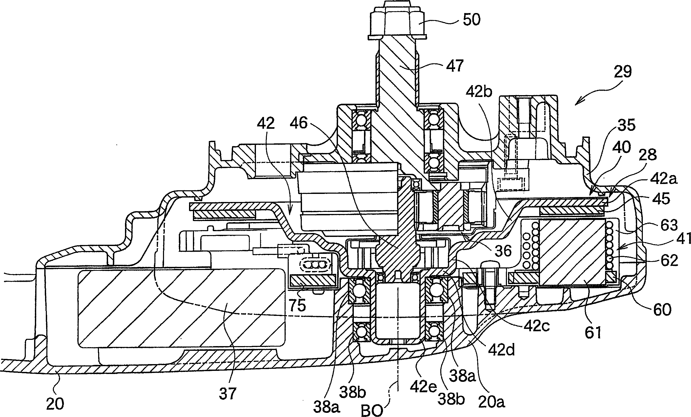
[0045] Next, embodiments of an axial gap type rotating electric machine according to the present invention will be described with reference to the drawings.

[0046] (first implementation)

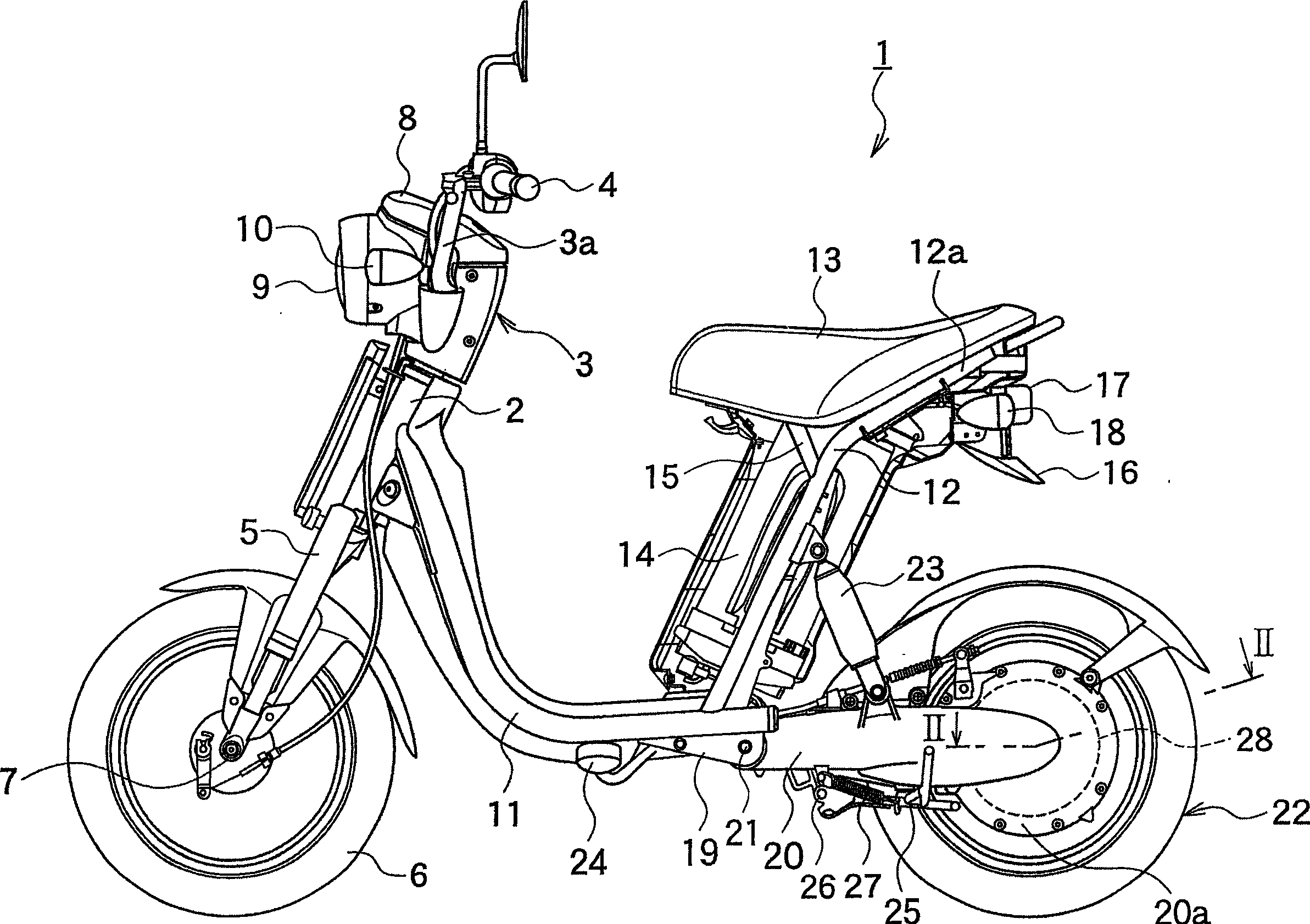
[0047] figure 1 It is a side view of an electric motorcycle 1 as an example of a device equipped with an axial gap type rotating electric machine according to the first embodiment of the present invention.

[0048] Such as figure 1 As shown, the electric motorcycle 1 is equipped with a front pipe 2 at the upper part in front of its vehicle body, and in this front pipe, a steering shaft not shown in the figure for changing the direction of the vehicle body is passed through freely rotatably. On the upper end of the steering shaft, a handle support portion 3 for fixing a handle 3a is attached, and handles 4 are attached to both ends of the handle 3a. In addition, the right side not shown in the figure ( figure 1 The handle 6 on the inner side) constitutes a rotatable throttle control han...


PUM


Abstract

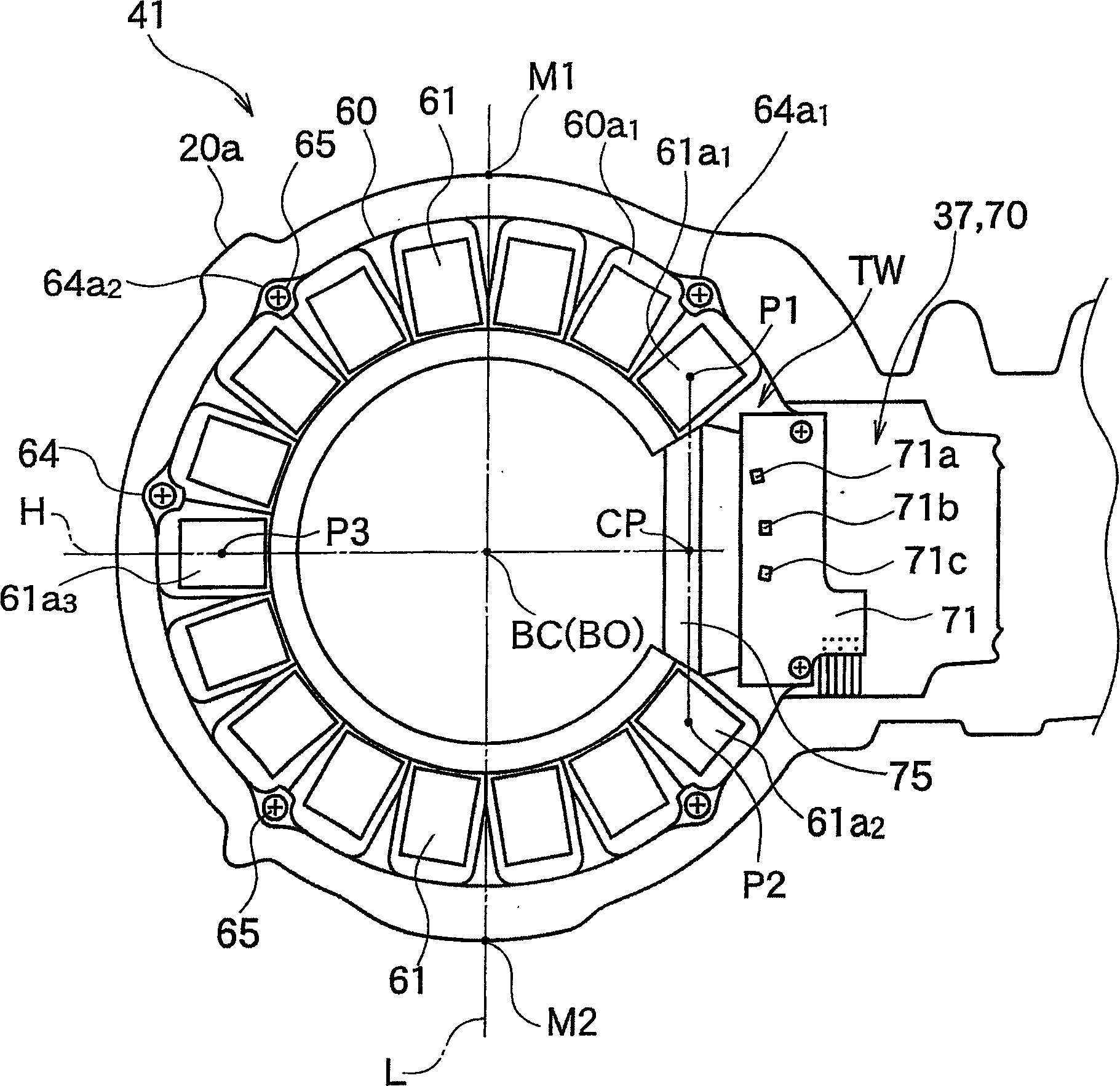
The invention relates to an axial gap dynamo-electric machine comprising a rotor having a revolving shaft supported by a bearing and a magnet for generating a magnetic field, a stator yoke disposed so as to oppose the rotor, and a plurality of teeth being disposed on the magnet-opposed surface of the stator yoke substantially in the shape of a partly removed circle, wherein a removed portion is free of teeth, the partially removed circle having a midpoint at a predetermined point in relation to a center axis of the bearing and opposing the magnet at a predetermined gap. The invention aims to provide an improved axial gap dynamo-electric machine having a structure in which some of the teeth in the stator are missing, to limit inclination of a rotor caused by such missing of the teeth. Therefore, the invention provides that circumferential pitches among the plurality of teeth are set to differ from each other, in particular, so that an attractive force of the magnet is set to increase towards the removed portion.

Description

technical field [0001] The present invention relates to an axial gap type rotating electric machine. Background technique [0002] As rotating electric machines used for driving sources of electric motorcycles and other general electric motors, axial gap type rotating electric machines are attracting attention in addition to conventional radial gap type rotating electric machines. [0003] As such an axial gap type rotating electrical machine, for example, an axial gap type electric motor has a structure of a rotor yoke (rotor side yoke) and a stator yoke (stator side yoke) of a rotating shaft supported on its bearings. yokes) are opposed to each other, and their opposing surfaces are perpendicular to the rotation axis. At the same time, on the opposing surface of the yoke on the rotor side, for example, a circular (or annular) field magnet is arranged, and on the opposing surface on the stator side, along the radial direction (radial direction) relative to the rotation axi...

Claims


Application Information

Patent Timeline
Patent Type & Authority Applications(China)
IPC IPC(8): H02K1/14H02K1/18H02K3/52H02K11/04H02K21/24
CPCH02K1/148H02K1/185H02K3/522H02K21/24B60L2200/12B60L2220/12B60L2240/423B60L2270/142B60L2270/145B60L50/66Y02T10/64Y02T10/70H02K11/05
Inventor 内藤真也日野阳至石原弘之室田圭子寺田润史小野朋宽
Owner YAMAHA MOTOR CO LTD
Learn More