Golf club head with improved mass distribution

a golf club head and mass distribution technology, applied in the field of golf club head design, can solve the problems of increased overall production cost, perceived instability, and undercut configuration of existing golf club head that does not provide optimal mass distribution

Inactive Publication Date: 2009-09-29
DUNLOP SPORTS CO LTD
View PDF44 Cites 26 Cited by
  • Summary
  • Abstract
  • Description
  • Claims
  • Application Information

AI Technical Summary

Problems solved by technology

Despite performance benefits such as increased moment of inertia about the center of gravity and improved feel, golf club head designs having undercut configurations of the corner-type may present problems in casting and manufacturing, thereby increasing overall production cost.
Undercut configurations of existing golf club heads do not provide optimal mass distribution with respect to heel-side and toe-side weighting.
The existing undercut configurations may interfere with the solid and continuous appearance of the golf club head, resulting in perceived instability and corresponding poor performance.
Undercut configurations of existing perimeter-weighted club heads do not provide adequate mass distribution relative to the heel and toe portions.

Method used


Image

  • Golf club head with improved mass distribution
  • Golf club head with improved mass distribution
  • Golf club head with improved mass distribution

Examples


Embodiment Construction

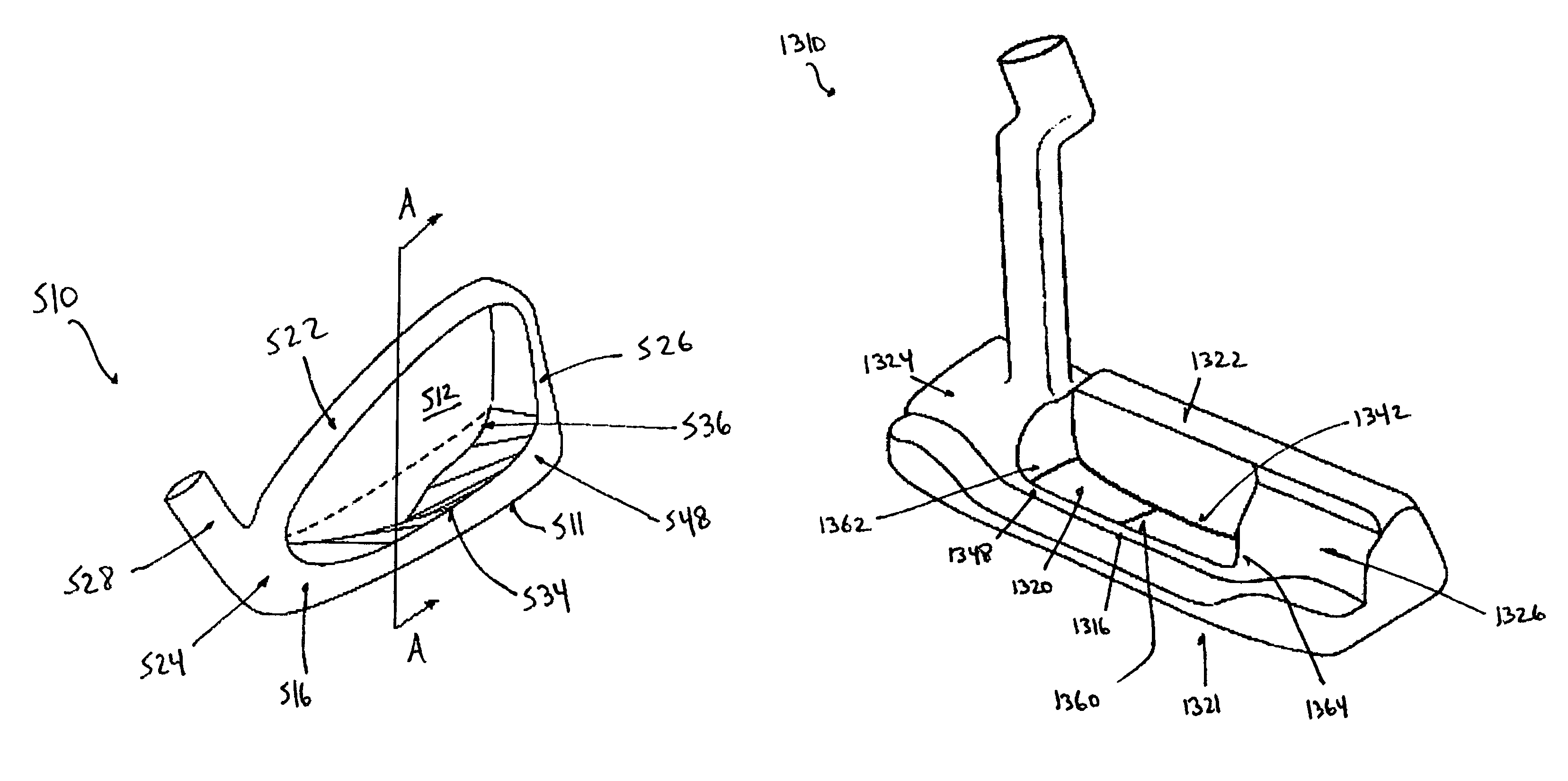
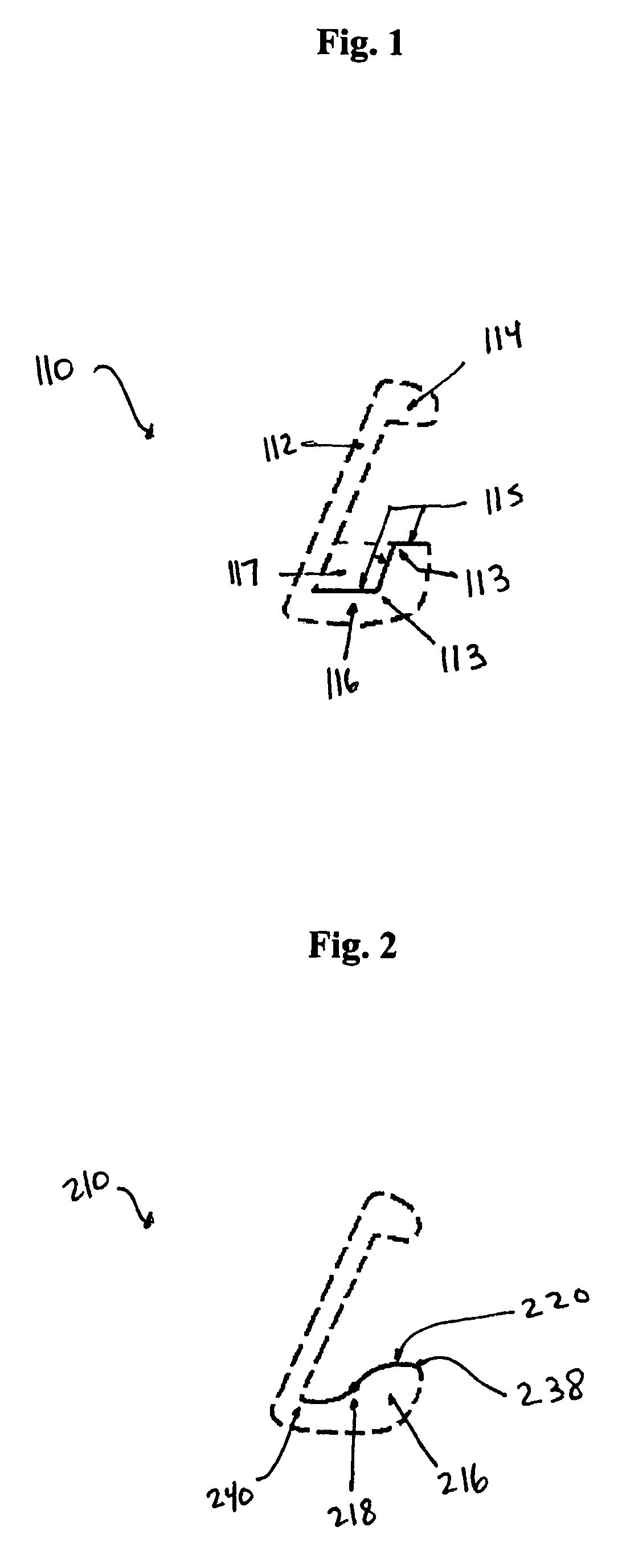
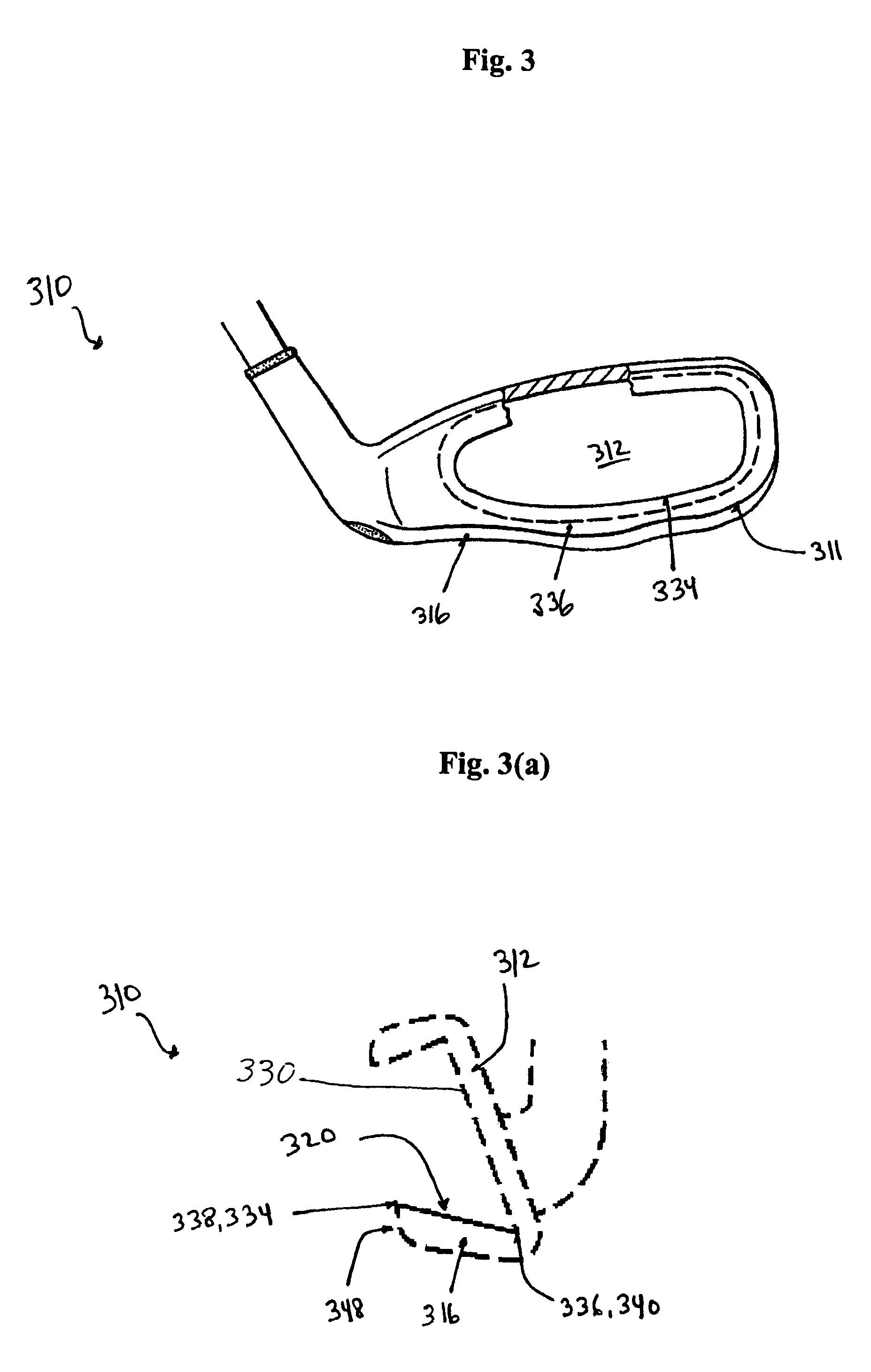
[0058]As shown in FIG. 2, a golf club head 210 is depicted in cross-section at address position. The golf club head 210 comprises a sole portion 216 with an upper surface 220. The cavity surface 220 on the upper and interior surface of sole portion 116 comprises curvilinear front-to-rear (FR) cross-sectional contour such that an apogee 238 of surface 220 lies rearward of a perigee 240 forming a sink or depression. Herein, a sink refers to a portion of the upper or cavity surface of the sole portion of a golf club head, having curvilinear or linear FR contour extending substantially from the forward-most end to the rearward-most end of the upper surface, in which the apogee of the upper surface lies rearward of the perigee in the address position for any FR cross-section within the sole portion.

[0059]A point of inflection may be present in that upper surface intermediate its forward-most and rearward-most ends. An inflection point 218 may be considered mathematically to represent a p...


PUM


Abstract

A golf club having a sole portion extending rearwardly from a rear surface of the head, wherein the sole portion includes a forward end, a rearward end, an upper surface and a lower surface. The intersection of the upper surface and the rear surface defines an interior sole lone. The intersection of the upper surface and the rearward end defines a trailing edge exterior sole line. The upper surface comprises a sink portion having substantial variation in heel-to-toe contour, including variation of at least one of: the height of the trailing edge or exterior sole line relative to the height of the interior sole line, measured in vertical alignment; the height of any of the interior sole line or trailing edge or exterior sole line relative to the height of the general outer periphery measured in vertical alignment; and concavity as defined by forward-to-rear contour.

Description

CROSS-REFERENCE TO RELATED APPLICATION[0001]The present application claims priority of U.S. Provisional Patent Application Ser. No. 60 / 598,897, filed Aug. 5, 2004, the entirety of the disclosure of which is hereby incorporated by reference into the present application.BACKGROUND[0002]The present invention relates to the design of golf clubs, and more particularly to the design of iron-type golf club heads and putters.[0003]The significance of improving the mass distribution of golf club heads is well-recognized in the art. For example, perimeter weighting elements in golf club heads are commonly used to increase moment of inertia and thereby provide enhanced resistance to twist, resulting in a more forgiving golf club head in the case of an off-center golf ball impact.[0004]Those skilled in the art have long recognized that a low and rearward center of gravity may provide performance benefits such as a higher launch angle for higher handicapped golfers, as well as improved feel. Som...

Claims


Application Information

Patent Timeline
Patent Type & Authority Patents(United States)
IPC IPC(8): A63B53/04
CPCA63B53/047A63B53/0487A63B59/0092A63B49/06A63B53/04A63B2053/0433A63B2053/0491A63B2053/0437A63B2053/045A63B60/52A63B60/54A63B53/0433A63B53/0437A63B53/045A63B60/00
Inventor SUKMAN, JESSE D.
Owner DUNLOP SPORTS CO LTD
Why Eureka
Try Eureka