Suspension system for a floating header on an agricultural implement

a technology of agricultural implements and suspension systems, applied in the field of agricultural implements, can solve the problems of increasing complexity, cost, and reliability declin

Active Publication Date: 2009-10-06
VERMEER MFG CO
View PDF32 Cites 36 Cited by
  • Summary
  • Abstract
  • Description
  • Claims
  • Application Information

AI Technical Summary

Problems solved by technology

The multiplicity of components for lifting and suspending a floating header on a fixed-frame agricultural implement increases complexity, cost, while decreasing reliability.

Method used


Image

  • Suspension system for a floating header on an agricultural implement
  • Suspension system for a floating header on an agricultural implement
  • Suspension system for a floating header on an agricultural implement

Examples


embodiment

Operational Process (Either Embodiment)

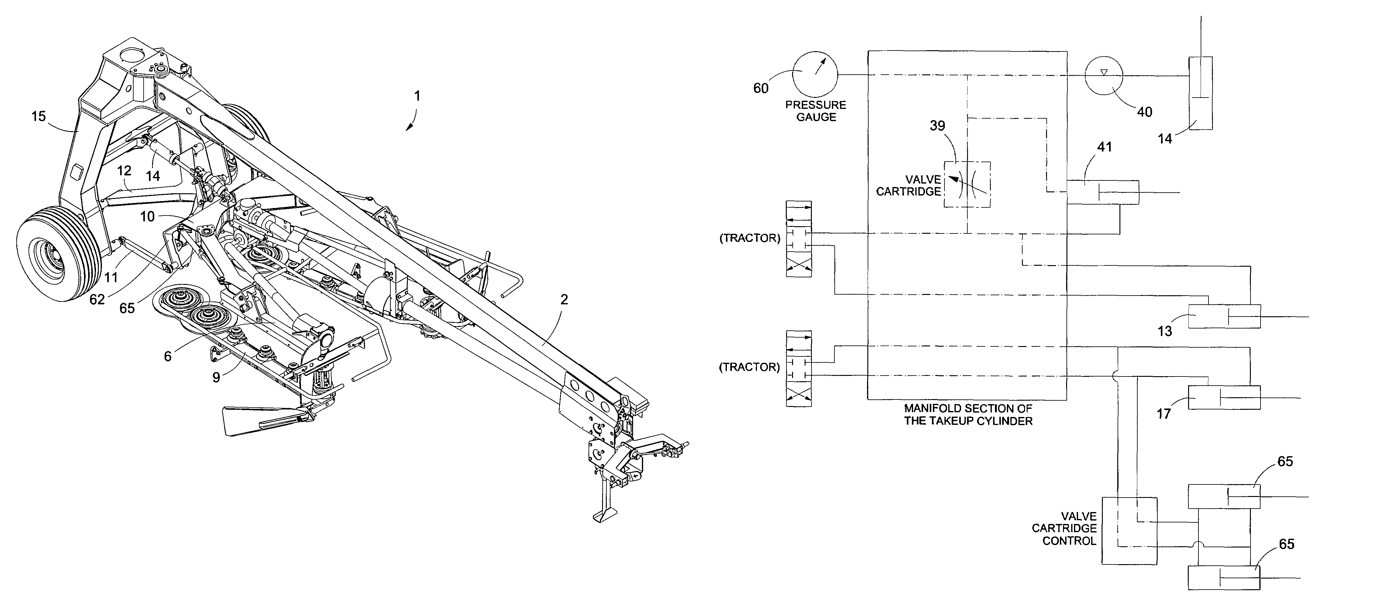
[0043]1) Open the take-up valve 39.[0044]2) Using the tractor as the power source, pressurize the mower hydraulic system. The sub-frame / header 6 will rise to a maximum height due to full retraction of the take-up cylinder 41 and to fully stroking the cylinders 14.[0045]3) Close the take-up valve 39.[0046]4) Put the tractor in float.[0047]5) Crack the valve 39 slowly to bleed excess pressure until the appropriate pressure is read from the gauge. The appropriate pressure will be established for each individual towed mower 1 model on which the present invention is incorporated.[0048]6) Lock the valve 39 at an appropriate pressure. The cutter bars 9 will contact the ground with the hydraulic suspension of the present invention giving it the appropriate amount of contact pressure. The mower 1 is operational.

[0049]As an alternative to step 2, using the tractor as the power source . . . , the pressure to the mower hydraulic system may be provided from...


PUM


Abstract

A suspension system for fixed-frame, towed agricultural implements having at least one floating head. A hydraulic cylinder is used for both lift and suspension of the floating head. A hydraulic accumulator provides expansion room for hydraulic fluid to move in and out of the hydraulic cylinder during suspension.

Description

CROSS REFERENCE TO RELATED APPLICATIONS[0001]U.S. patent application Ser. No. 11 / 927,866 filed Oct. 30, 2007 (Our Ref. 2-5169-110), is hereby incorporated by reference herein in its entirety.STATEMENT REGARDING FEDERALLY SPONSORED RESEARCH OR DEVELOPMENT[0002]Not applicable.REFERENCE TO MICROFICHE APPENDIX[0003]Not applicable.BACKGROUND OF THE INVENTION[0004]1. Field of the Invention[0005]The present invention relates generally to an agricultural implement, including a floating header. More particularly, the present invention relates to an improved suspension system for agricultural implements having one or more floating headers wherein the suspension hydraulic cylinders are also used to lift the header for transport.[0006]2. Background Art[0007]A three-point mounted mower with a suspension system is disclosed in U.S. patent application Ser. No. 5,417,042. Disclosed in this application is an example of a mower suspension system with separate elements having a first and a second cham...

Claims


Application Information

Patent Timeline
Patent Type & Authority Patents(United States)
IPC IPC(8): A01D34/00
CPCA01D34/661A01B63/32
Inventor BOLLINGER, SHANE A.THOMPSON, KENT L.BENTZINGER, RUSTIN V.
Owner VERMEER MFG CO
Why Eureka
Try Eureka