Wheel bearing joint unit

a joint unit and bearing technology, applied in the direction of mechanical equipment, couplings, transportation and packaging, etc., can solve the problems of screw connection deformation, adversely affecting the position and shape of the joint component, adversely affecting the engagement, etc., and achieve the effect of increasing the tightening torqu

Active Publication Date: 2009-10-06
SCHAEFFLER TECH AG & CO KG
View PDF21 Cites 20 Cited by
  • Summary
  • Abstract
  • Description
  • Claims
  • Application Information

AI Technical Summary

Benefits of technology

[0010]The first extension is preferably of annular design rotationally symmetrical with respect to the rotational axis of the wheel bearing joint unit. One embodiment provides that the first extension is at least partially delimited radially at the outside by the outer lateral surface of a truncated cone. The stress distribution from axial preload is thus optimized in the extension.
[0012]The object of the invention is also achieved by means of the features of an independent claim which relates to the design of the contact of the screw element against the hub or against at least one intermediate element which bears between the head and the hub. A combination of the previously described features with the features of the independent claim is also alternatively provided.

Problems solved by technology

The high forces lead to deformations in the screw connection.
The deformations on the joint component under some circumstances adversely affect the position and shape of the joint component.
Plastic or elastic deformations on the thread or on the surroundings of the thread are transmitted to the toothing and adversely affect the engagement.
Non-uniform distributions of stresses in the material of the screw connection and its surroundings can lead to a decrease in the axial preload and to damaging stress peaks in the connection.

Method used


Image

  • Wheel bearing joint unit
  • Wheel bearing joint unit
  • Wheel bearing joint unit

Examples


Embodiment Construction

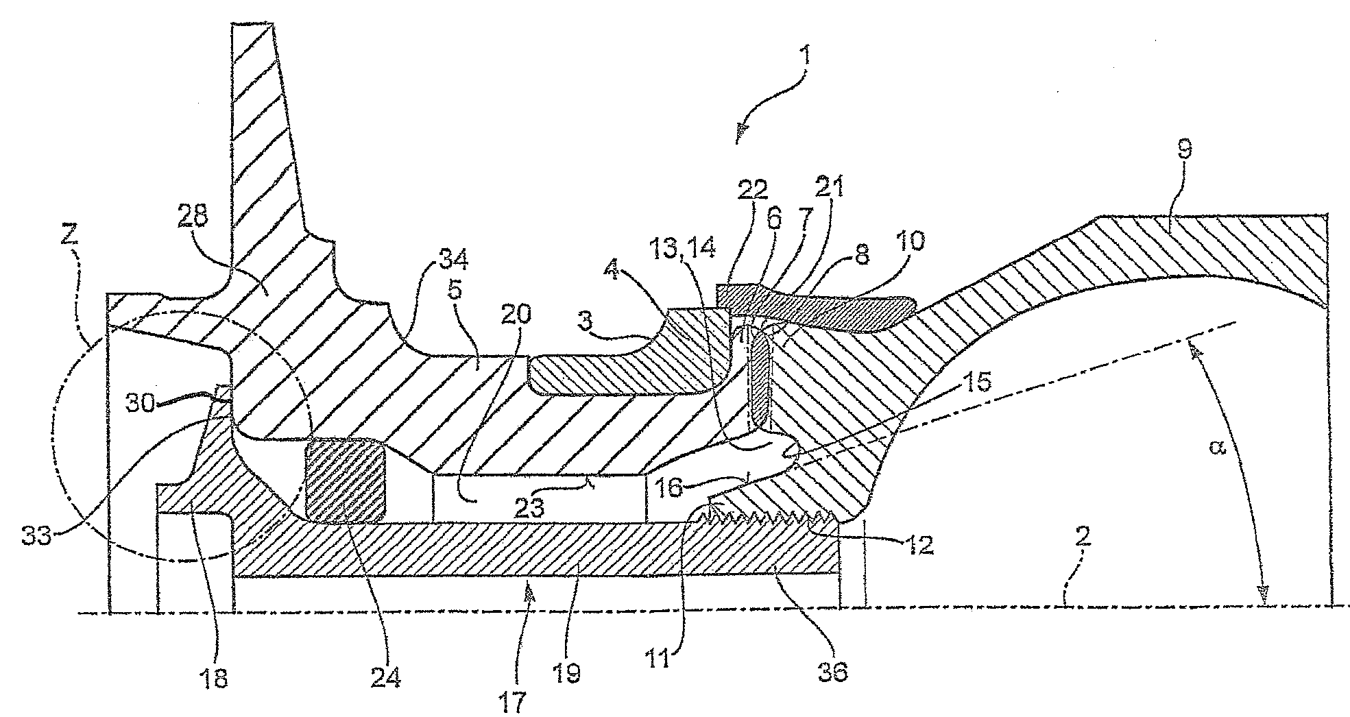
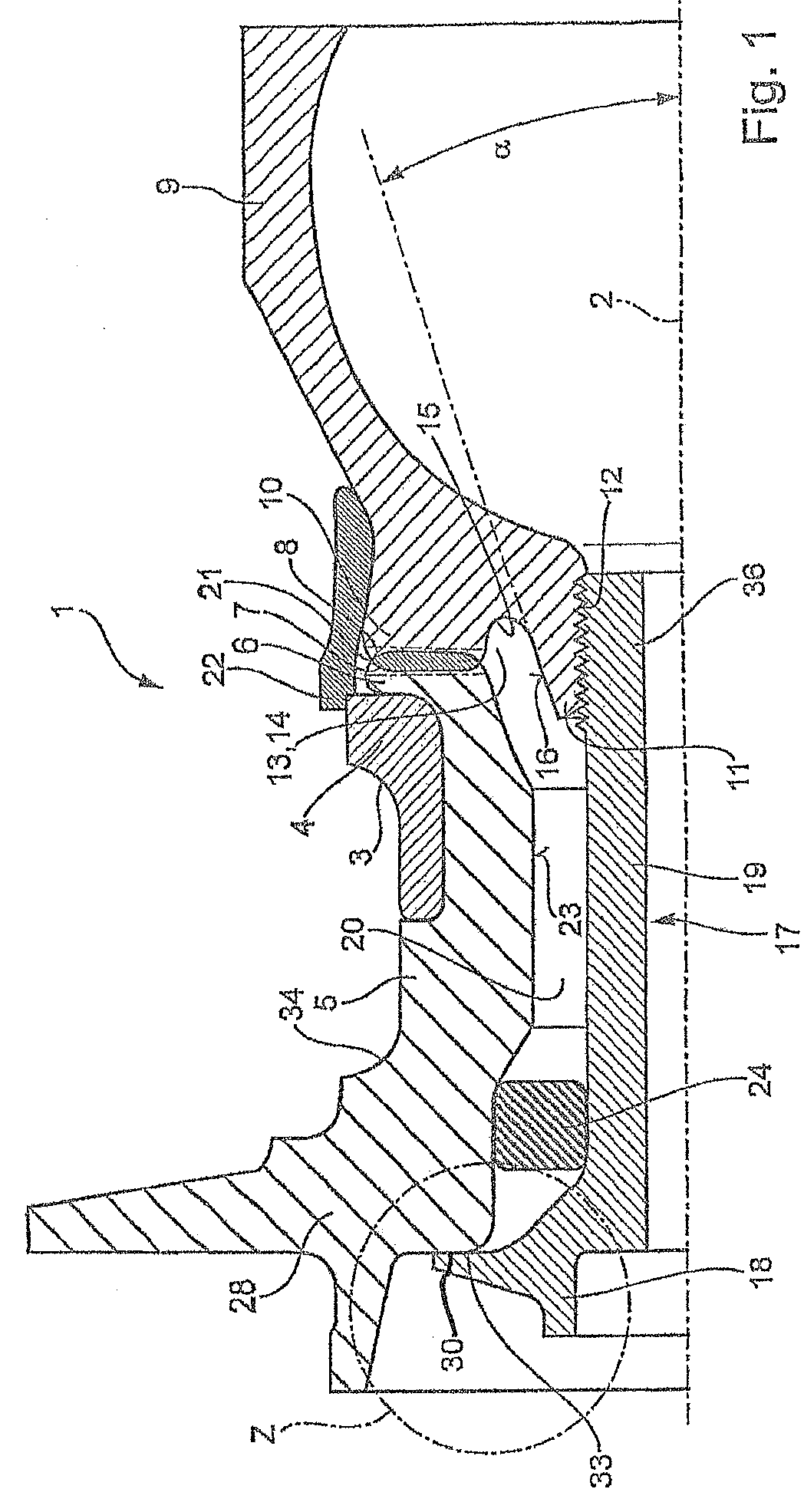
[0020]The invention is explained in more detail below on the basis of exemplary embodiments. FIG. 1 shows a partial section through an exemplary embodiment of a wheel bearing joint unit 1 longitudinally along the rotational axis 2 of the wheel bearing unit 1. The wheel bearing unit 1 has two raceways 3 and 34 for rows of rolling bodies (not illustrated). One raceway 3 is formed on an inner ring 4. The inner ring 4 is seated radially on a hub 5 of the wheel bearing joint unit 1. The inner ring 4 is held axially on the hub 5 by means of a collar 6. Formed on the collar 6 is a spur toothing 7 (not described in any more detail). The spur toothing 7 engages into a mating toothing 8 on a joint component 9 in the form of a joint bell. The mating toothing 8 is formed on an extension 10 which projects axially from the joint bell. A further extension 11 with an internal thread 12 is formed on the joint component 9.

[0021]The two extensions 10 and 11 are of annular design and rotationally symme...


PUM


Abstract

The wheel bearing joint unit having an inner ring that sits on a hub of the wheel bearing joint unit. The inner ring is axially retained on the hub using a collar that is formed from the hub. The collar is provided with a toothing which meshes with a corresponding opposite toothing on a joint part. The toothing and the opposite toothing are braced against each other by a screw which rests on the hub and engages into a thread on the joint part. The joint has two axial projections, one which has the toothing to engage the toothing on the collar and another with the threading to engage the screw. These two projections are spaced apart by a groove to provide flexibility.

Description

FIELD OF THE INVENTION[0001]A wheel bearing joint unit having at least one inner ring which is seated on a hub of the wheel bearing joint unit, with the inner ring being held axially on the hub by means of a collar which is formed out of the hub, and the collar having a toothing in engagement with a corresponding mating toothing on a joint component, and with the toothing and the mating toothing being braced against one another by means of at least one screw element which is supported on the hub and engages into a thread on the joint component.BACKGROUND OF THE INVENTION[0002]A wheel bearing joint unit of said type is described in DE 36 36 243 A1. The screw element is generally a bolt with a head and with a thread on a shank. The head of the bolt bears flat, in a screwed fashion, with a generally vertical planar contact face against a correspondingly vertical planar support face of the hub. The joint component is for example the bell of a constant-velocity joint. Formed in the base ...

Claims


Application Information

Patent Timeline
Patent Type & Authority Patents(United States)
IPC IPC(8): F16D3/84
CPCB60B27/00F16D3/22F16D1/076B60B35/14B60B35/00F16C11/06
Inventor LANGER, ROLANDMASUR, ERNSTHEISS, RALFFUELLER, BENNONIEBLING, PETER
Owner SCHAEFFLER TECH AG & CO KG
Why Eureka
Try Eureka