Method of calibrating a motorized roller shade

a technology of roller shades and roller tubes, applied in the direction of motor/generator/converter stoppers, dynamo-electric converter control, door/window protection devices, etc., can solve the problem that shades having tubes of different diameters cannot raise or lower the shade fabric at the same speed, and are not supported throughout their length

Active Publication Date: 2009-10-06
LUTRON TECH CO LLC
View PDF22 Cites 67 Cited by
  • Summary
  • Abstract
  • Description
  • Claims
  • Application Information

AI Technical Summary

Problems solved by technology

Roller tubes, however, are generally supported only at their ends and are otherwise unsupported throughout their length.
Roller tubes, therefore, are susceptible to sagging if the cross-section of the roller tube does not provide for sufficient bending stiffness for a selected material.
However, two roller shades having tubes of differing diameter will not raise or lower a shade fabric at the same speed if they are rotated at the same rotational speed.
The ability to provide constant shade speed for two roller shades having tubes of differing diameters is further complicated because the shade speed for either one of the roller shades will not remain constant as the shade is raised or lowered between two shade positions.
Accordingly, this increases the time required for the manufacturing process and increases the cost of the motorized rollers shades.
Further, there are some installation factors that usually cannot be determined at the time of manufacturing, but still affect the values of the roller tube diameter, the shade fabric thickness, and shade fabric length.

Method used


Image

  • Method of calibrating a motorized roller shade
  • Method of calibrating a motorized roller shade
  • Method of calibrating a motorized roller shade

Examples


second embodiment

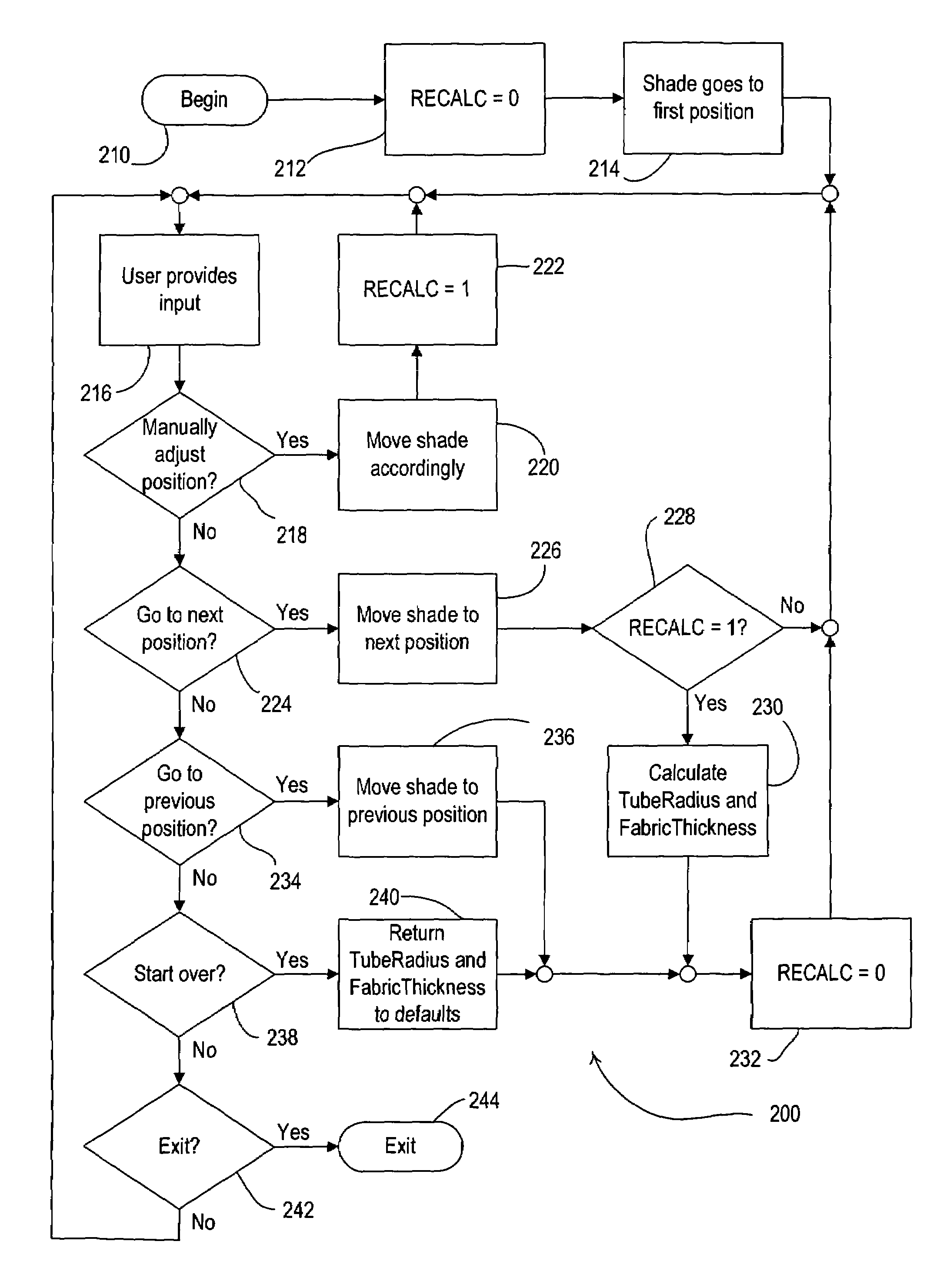
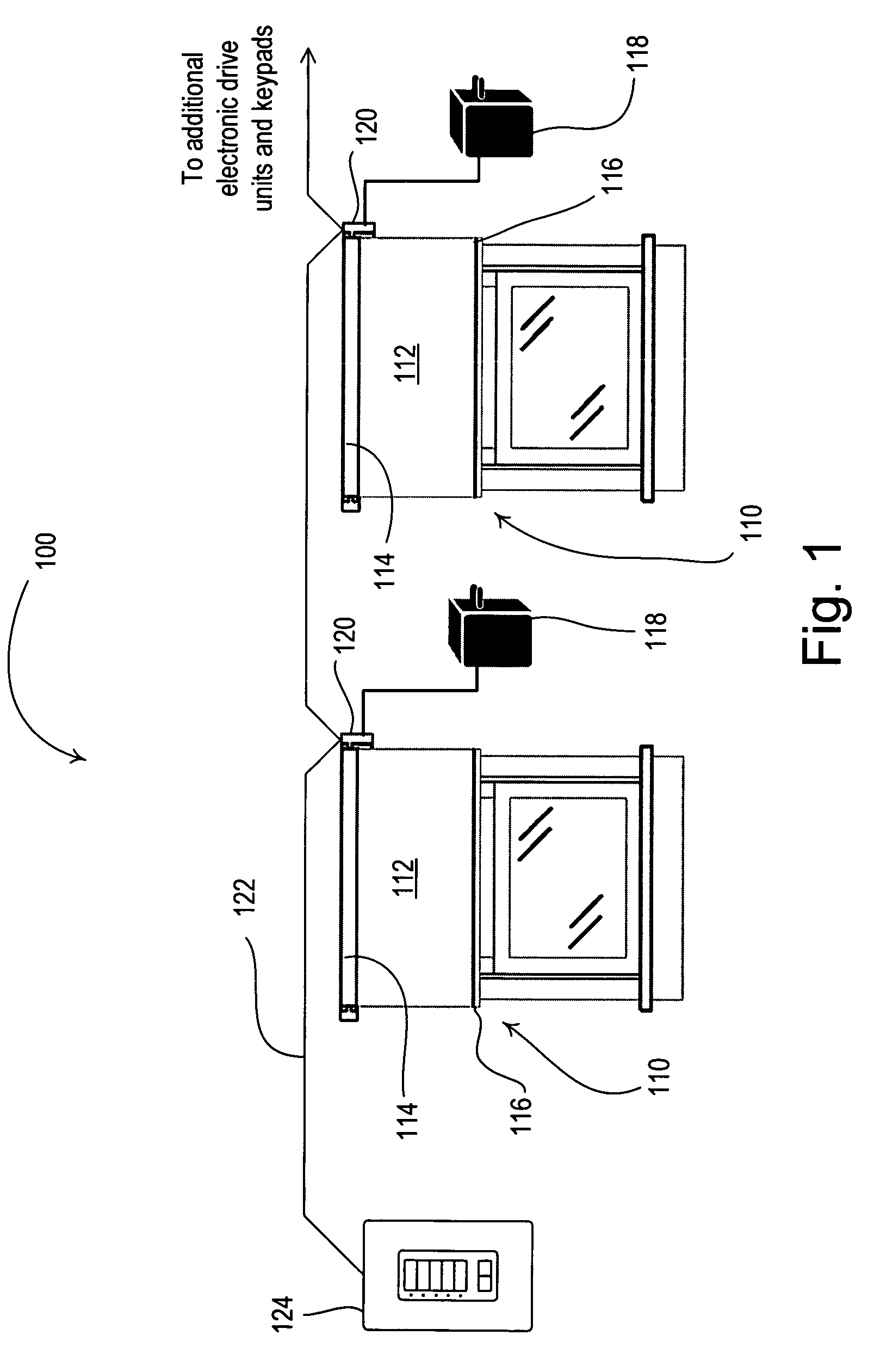
[0052]FIG. 7 is a flowchart of a calibration procedure 300 for the motorized window shade 110 according to the present invention. In order to execute the calibration procedure 200, the control system 100 includes a computing device, such as a personal computer (not shown), operable to communicate with the electronic drive units 120 of the motorized window shades 110. The personal computer includes a graphical user interface (GUI) for providing a simple set of steps for a user to complete in order to calibrate the motorized roller shade 110. The calibration procedure 300 begins at step 310 when the user enters a start command via the GUI. The shade is first moved to an initial position, e.g., preferably the fully closed position, at step 312, and the user notes at step 314 the position of the hembar 116 of the shade fabric 112. For example, the user notes that the hembar 116 is one inch above a windowsill when the shade fabric 112 is in the closed position. Next, the shade is moved t...

third embodiment

[0053]FIG. 8 is a flowchart of a method 400 of calculating the tube radius r and the fabric thickness t according to the present invention. Preferably, the method 400 is used in place of step 230 of the calibration procedure 200 of FIG. 5. The calculation procedure 400 is very similar to the calculation procedure shown in FIG. 6. However, the calculation procedure 400 averages the values computed at each of the data points to determine the tube radius r and the fabric thickness t.

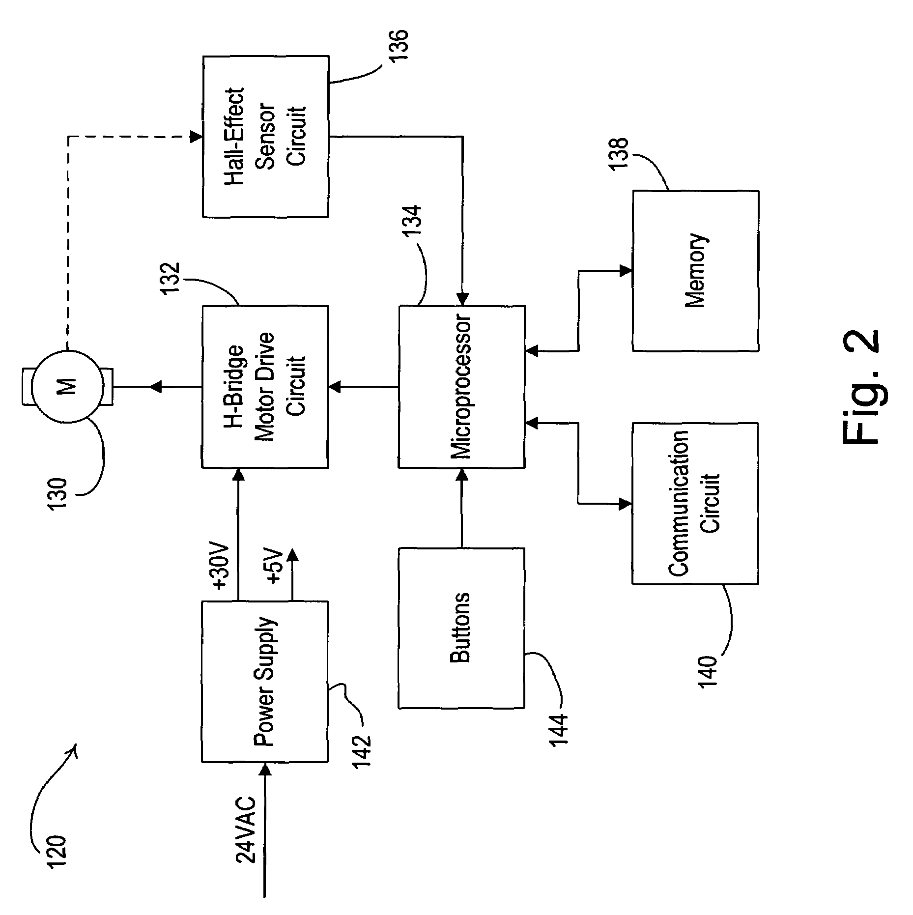
[0054]Specifically, at step 462, the microcontroller 134 solves Equations 3 and 4 using two data points to determine a tube radius rn and a tube thickness tn. Accordingly, the tube radius rn and the tube thickness tn are calculated at multiple data points, such as, for example, four data points, where a fourth tube radius r4 and a fourth tube thickness t4 are determined from the fourth data point. At step 646, the microcontroller 134 averages all of the values of the tube radius rn and the tube thickness tn...


PUM


Abstract

Calibration of a motorized roller shade is accomplished by calculating a radius of a roller tube and thickness of a shade fabric rotatably supported by the roller tube. First, a lower edge of the shade fabric is moved to a first position at a first linear distance from a predetermined position. Second, a first number of revolutions of the roller tube between the first position and the predetermined position is determined. Next, the lower edge of the shade fabric is moved to a second position at a second linear distance from the predetermined position and a second number of revolutions between the second position and the predetermined position is determined. Finally, the tube radius and the fabric thickness are calculated from the first and second linear distances and the first and second numbers of revolutions. The tube radius and the fabric thickness are used to control the linear speed of the lower edge of the shade fabric.

Description

BACKGROUND OF THE INVENTION[0001]1. Field of the Invention[0002]The present invention relates to a method of controlling motorized window shades, and more specifically, a method of calibrating a motorized roller shade in order to determine a radius of the roller tube and a thickness of the shade fabric.[0003]2. Description of the Related Art[0004]Motorized roller shades include a flexible shade fabric wound onto an elongated roller tube. The roller tube is rotatably supported so that a lower end of the shade fabric can be raised and lowered by rotating the roller tube. The roller tubes are generally in the shape of a right circular cylinder having various lengths for supporting shade fabrics of various width. Motorized roller shades include a drive system engaging the roller tube to provide for tube rotation. The shade fabric is typically moved between an open position and a closed position.[0005]For aesthetic reasons, it is desirable that the outer diameter of the roller tube be as...

Claims


Application Information

Patent Timeline
Patent Type & Authority Patents(United States)
IPC IPC(8): H02P7/00A47G5/02H02P3/00
CPCE06B9/68G05B2219/45242E06B2009/2458
Inventor MOSELEY, ROBIN C.MOSELEY, LEGAL REPRESENTATIVE, WENDY MARGARETKIRBY, DAVID A.MIERTA, JUSTINBRENNER, THOMAS W.
Owner LUTRON TECH CO LLC
Why Eureka
Try Eureka