Locking assembly for stanchion

a technology of locking assembly and stanchion, which is applied in the direction of couplings, rod connections, machine supports, etc., can solve the problems of inconvenient manual application of conventional locking assemblies, hazardous conditions, and severe damage to umbrellas

Active Publication Date: 2009-10-13
TUUCI WORLDWIDE LLC
View PDF47 Cites 21 Cited by
  • Summary
  • Abstract
  • Description
  • Claims
  • Application Information

AI Technical Summary

Benefits of technology

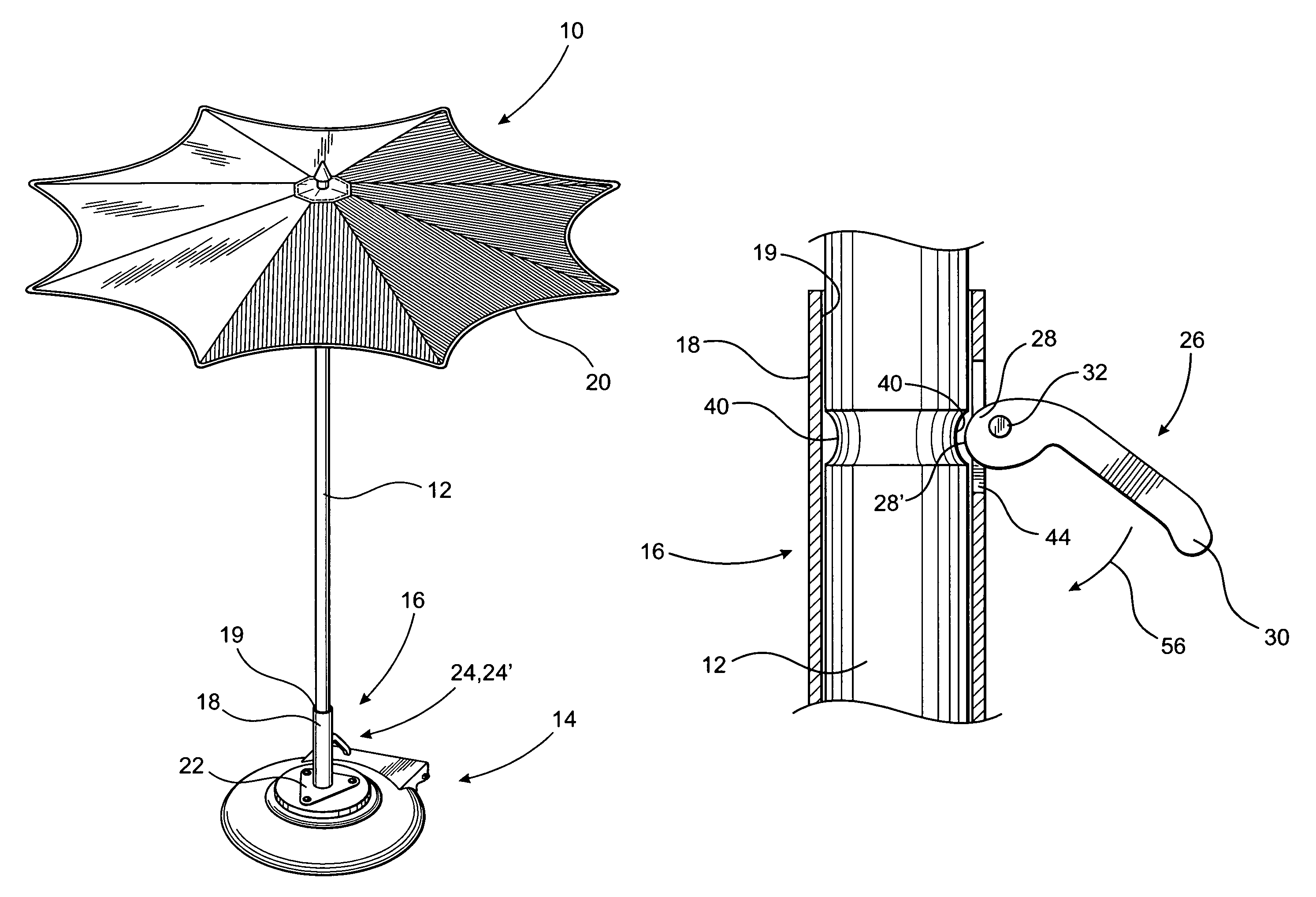
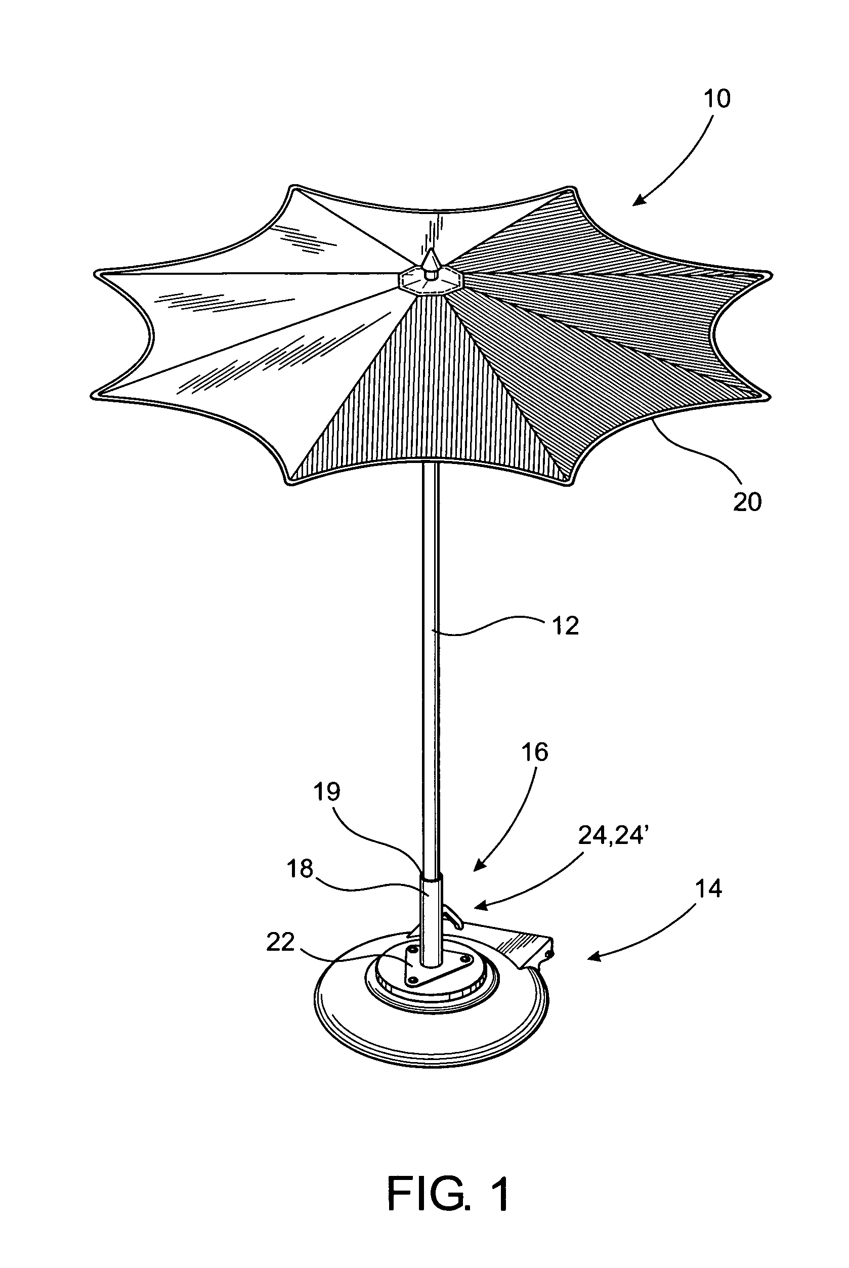
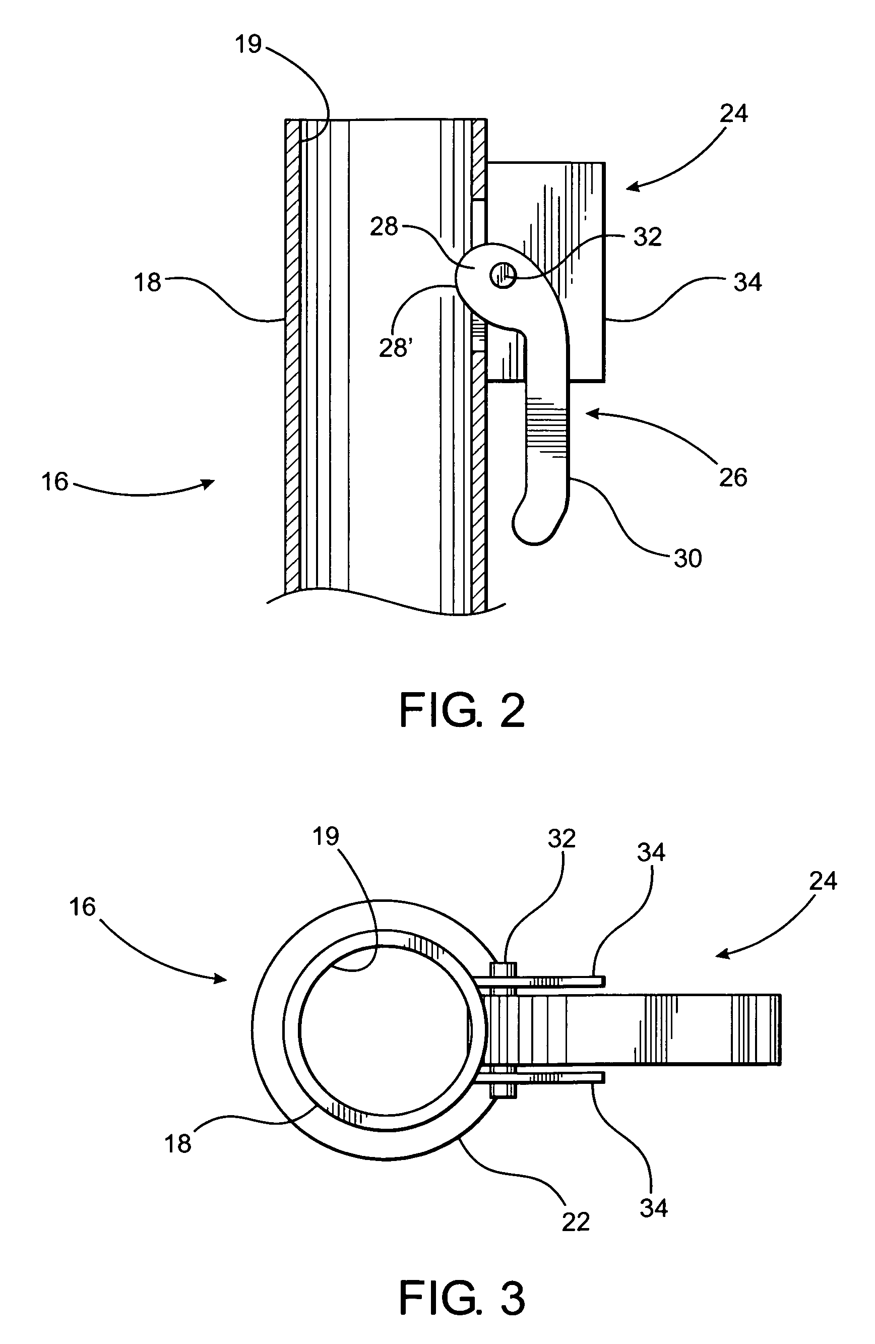
[0011]This invention is directed to a locking assembly intended primarily for use with large outdoor umbrellas in hopes of presenting a solution to the long felt needs described above. As such, the present invention is structured to automatically secure the mast of an umbrella or other stanchion-like structures to a supporting base or like anchoring assembly, and preferably, also in a manner which allows for it to be removed therefrom, when that is desired. While a most preferred embodiment of the present invention will be described with specific reference to a support pole or mast associated with an outdoor umbrella, it is emphasized that the locking assembly of the present invention can be utilized to removably, securely and automatically connect a variety of different stanchion-like structures to a supporting and / or anchoring base, the base preferably being of the type incorporating a sleeve-like mounting structure.
[0012]As such, the mounting sleeve is structured to receive a free, distal end of the mast or stanchion within its interior. The umbrella or other assembly associated with the stanchion is thereby removably connected to the base in a secure and safe manner. Distinguishing structural features of the locking assembly further facilitate the quick and easy removal and release of the mast or stanchion with minimal manual manipulation thereof. For purposes of clarity, the term “stanchion” will be used to generally describe any of a plurality of masts or support poles associated with an outdoor umbrella or any type of elongated, substantially upright supporting structure associated with a variety of devices or assemblies, other than outdoor umbrellas.
[0014]Further, the locking assembly includes a locking member pivotally or otherwise movably disposable between what may be referred to as a locked orientation and a released orientation. As will be explained in greater detail hereinafter, the locked orientation of the locking member may be at least partially defined by an end or head portion of the locking member is disposed in interruptive engagement with an exterior portion of the stanchion which is disposed on the interior of the mounting structure. In contrast, the aforementioned released orientation of the locking member may be defined by a sliding engagement of the end or head portion or other portion of the locking member with an exterior portion of the stanchion disposed within the mounting structure. When in the released orientation the locking member will not interruptively interfere with the movement of the end portion of the stanchion into or out of the mounting structure. In addition and as also explained in greater detail hereinafter, in at least one embodiment of the locking assembly, the aforementioned released orientation may also be defined by disposition of the end or head portion of the locking member substantially out of engagement with the distal end of the stanchion and at least partially out of the interior of the mounting structure. It is of further note that the mounting structure may comprise an elongated sleeve like configuration having an open end and a hollow interior along at least a portion of the length thereof. However, the mounting structure can be defined by a variety of other structures, configurations, dimensions, etc. as long as there is cooperative structuring and functioning between the distal end or other engaged portion of the stanchion and the mounting structure which facilitates interconnection, support and positioning of the stanchion relative to the base in an intended manner.
[0015]As set forth above, one feature of a most preferred embodiment of the locking assembly of the present invention comprises the ability to automatically secure and removably connect or “lock” the stanchion to the base through interconnection with the mounting structure. This automatic, secure connection is accomplished without the need for manual manipulation of the locking assembly or any parts associated therewith. Similarly, the reliability of the locking assembly of the present invention provides enhanced safety features which require manual positioning of the locking member into the aforementioned released position, thereby ensuring that the stanchion cannot be inadvertently removed or detached from the supporting base due to ambient wind conditions or accidentally by an attending individual.
[0017]Accordingly, many of the various problems and disadvantages associated with conventional and prior art devices and assemblies for connecting a stanchion to a support base or like anchoring structure are overcome by virtue of the automatically operable locking assembly, as described in greater detail hereinafter with reference to the accompanying drawings. Further, a secure but removable interconnection of the stanchion to the supporting base is accomplished, while preventing inadvertent removal thereof by requiring at least a minimal manual manipulation of the locking assembly into the released orientation.

Problems solved by technology

More specifically, absent an effective locking assembly, an open umbrella can be subjected to sufficient lifting forces to cause a separation of the umbrella from the base.
Clearly, the inadvertent separation of the umbrella from the supporting base has the potential to present hazardous conditions, both to individuals and / or other property within the area, as well as the potential to severely damage the umbrella itself.
Such manual application of the conventional locking assemblies is inconvenient, relatively time consuming and frequently difficult to accomplish by a single individual installing the umbrella on the supporting base.
Also, because of the inconvenience associated with such manual manipulation, irresponsible individuals may not properly secure such known locking devices in the required fashion.
If not properly secured, the conventional locking assemblies may be inadequately positioned to accomplish the intended locking attachment of the umbrella to the base in a manner which will prevent inadvertent removal of the umbrella.

Method used


Image

  • Locking assembly for stanchion
  • Locking assembly for stanchion
  • Locking assembly for stanchion

Examples


Embodiment Construction

[0041]As shown in the accompanying drawings, the present invention is directed to a locking assembly which is structured to removably secure an outdoor umbrella or like structure 10 in an operative position, as demonstrated in FIG. 1. More specifically, a central or otherwise positioned mast, support pole or stanchion 12 is removably secured to a supporting base 14 by being interconnected thereto through the provision of a mounting structure, generally indicated as 16.

[0042]As is well-known, an umbrella assembly 10, especially when utilized in an outdoor environment, can be subjected to lifting forces and the like even during light to moderate wind conditions, when the canopy 20 is in its expanded or operative position. At times, such external forces can have the strength and ability to separate the mast 12 from the supporting base 14 by detachment from the mounting structure 16. Such inadvertent removal or detachment of the umbrella assembly 10 from its intended, supported position...


PUM


Abstract

An locking assembly structured to removably and automatically secure an umbrella mast or other stanchion to a supporting base including a mounting structure secured to the base in interconnecting relation between the stanchion and the base. The locking assembly is connected to the mounting structure and includes a movable locking member positionable between a locked orientation and a released orientation. The locked and released orientations are respectively and at least partially defined by the locking member disposed into and out of interruptive engagement with a predetermined exterior surface portion of the stanchion on an interior of the mounting structure. Automatic disposition of the locking member between the released and locked orientations is facilitated by an end portion of the locking member configured and structured to both slidingly and interruptively engage the stanchion.

Description

CLAIM OF PRIORITY[0001]The present application is based on and a claim of priority is made under 35 U.S.C. Section 119(e) to a provisional patent application currently pending in the U.S. Patent and Trademark Office, namely, that having Ser. No. 60 / 765,839 and a filing date of Feb. 7, 2006.BACKGROUND OF THE INVENTION[0002]1. Field of the Invention[0003]This invention relates to an assembly structured to removably and automatically secure the mast or center pole of an umbrella, or other stanchion type structure whether or not associated with an umbrella, to a supporting base. At least one locking member is disposed and configured to automatically, movably and interruptively engage predetermined exterior surface portions of the mast or stanchion as it is being mounted on the base. The need for a manual positionable locking device, such as a locking pin, threaded locking knob or like connector is thereby eliminated.[0004]2. Description of the Related Art[0005]The use of large outdoor u...

Claims


Application Information

Patent Timeline
Patent Type & Authority Patents(United States)
IPC IPC(8): F16M13/00
CPCA45B25/00F16B7/105A45B2200/109Y10T403/608F16B21/16
Inventor CLARKE, DOUGAN
Owner TUUCI WORLDWIDE LLC
Why Eureka
Try Eureka