

Foot-driven device for displacing a paper shredder bin
a technology of paper shredder and pedal, which is applied in the field of foot-driven pedal for displacing an inner bin from a paper shredder bin, can solve the problems of not providing a functional use as a waste bin and causing considerable trouble, and achieve the effect of facilitating the throwing of was
- Summary
- Abstract
- Description
- Claims
- Application Information
AI Technical Summary
Benefits of technology
Problems solved by technology
Method used
Image

Examples
Embodiment Construction
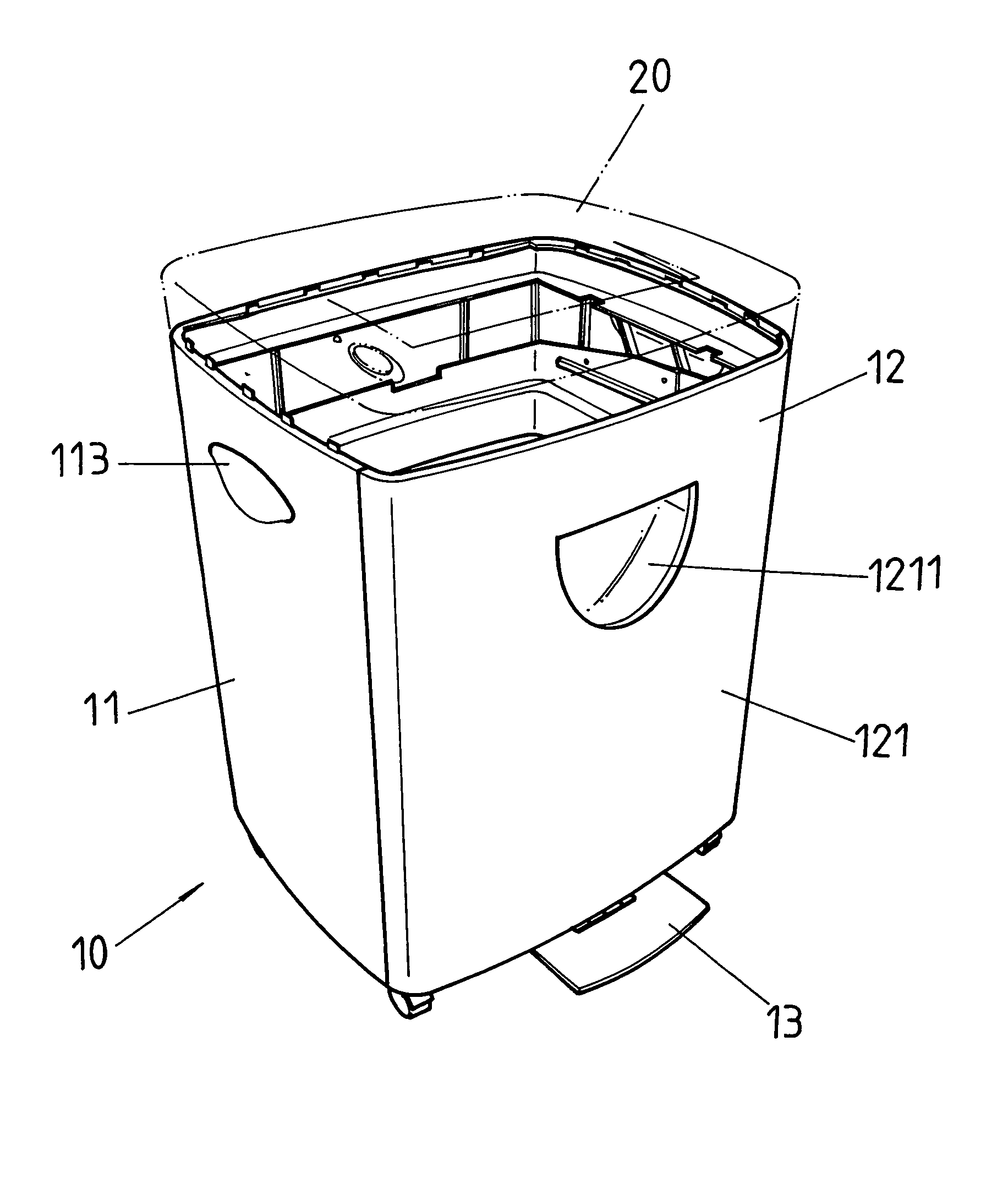
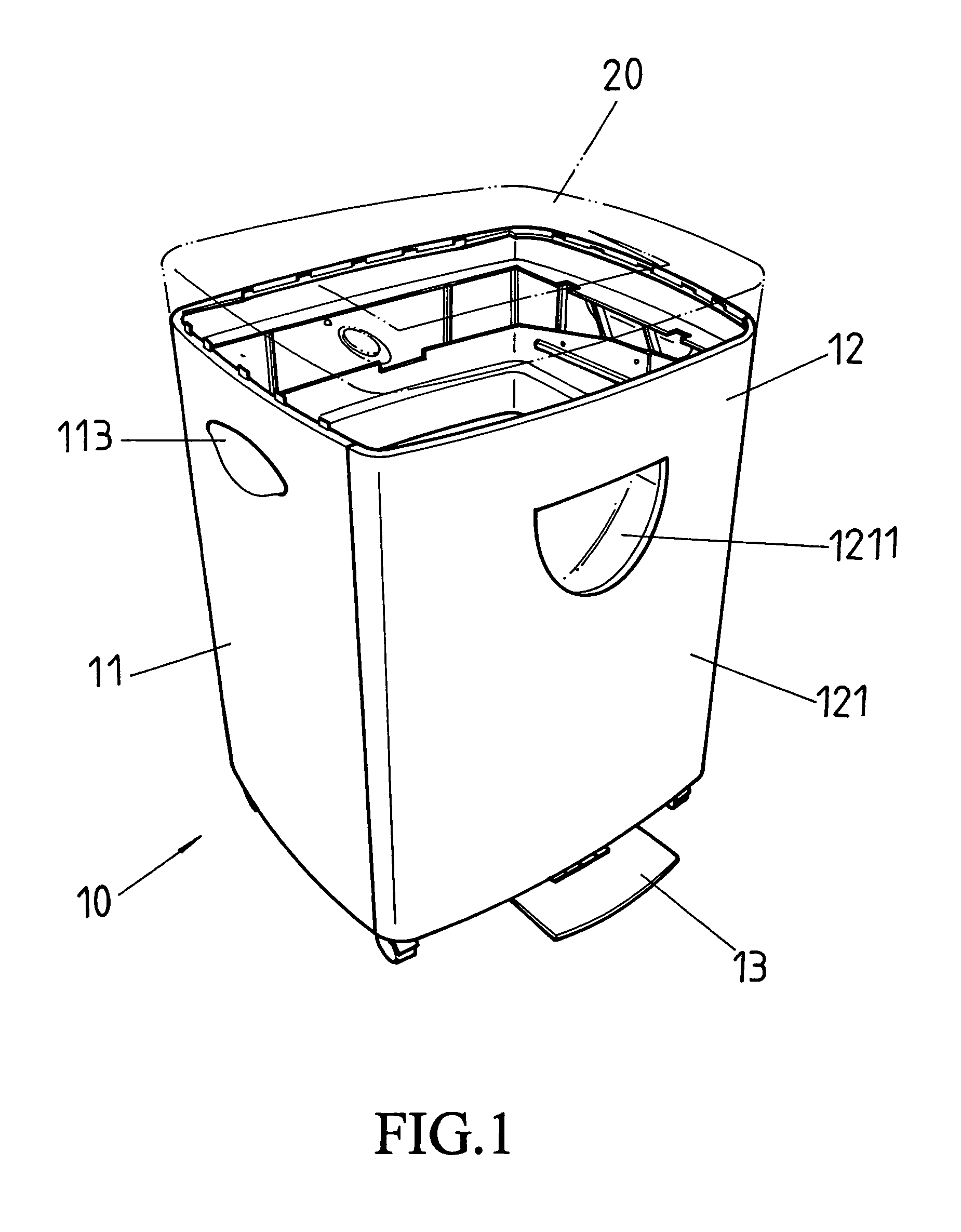
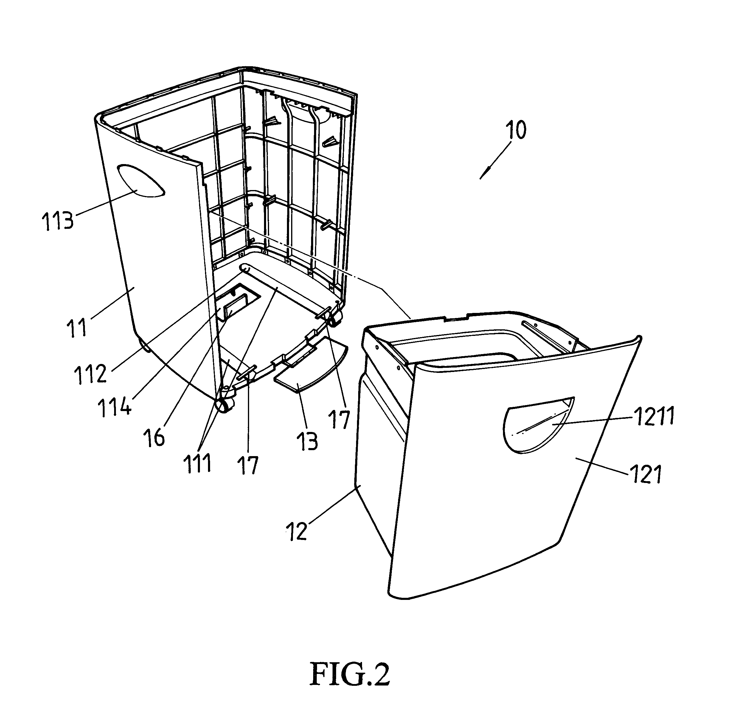
[0011]Referring to FIGS. 1 and 2, which show a paper shredder bin 10 of the present invention, on top of which is disposed a paper shredder 20. The paper shredder bin 10 is structured to comprise an outer frame 11 and an inner bin 12. A front side and a top end of the outer frame 11 are open ended, and two straight slide grooves 111 are defined on an upper side of a bottom portion of the outer frame 11. A position fixing hole 112 is defined in an inner side of each of the slide grooves 111. The inner bin 12 is an open top end bucket, a front portion of which is provided with a front panel 121, and a bottom portion of the inner bin 12 is provided with two straight slide tracks 122 (see FIG. 3). A slide wheel 123 is located at an inner edge of each of the slide tracks 122, thereby enabling the slide tracks 122 of the inner bin 12 to slide into the respective slide grooves 111 of the outer frame 11. Moreover, the slide wheels 123 slide within the slide grooves 111 and are able to respe...
PUM
 Abstract
Description
Claims
Application Information