Ceiling fan motor

a ceiling fan and motor technology, applied in the field of ceiling fan motors, can solve the problems of increasing the cost and the weight of the motor

Active Publication Date: 2009-11-03
YAO CHAO CHIN
View PDF10 Cites 3 Cited by
  • Summary
  • Abstract
  • Description
  • Claims
  • Application Information

AI Technical Summary

Problems solved by technology

This contributes to increases in the cost and the weight of the motor 100.

Method used


Image

  • Ceiling fan motor
  • Ceiling fan motor
  • Ceiling fan motor

Examples


Embodiment Construction

[0015]Before the present invention is described in greater detail, it should be noted that like elements are denoted by the same reference numerals throughout the disclosure.

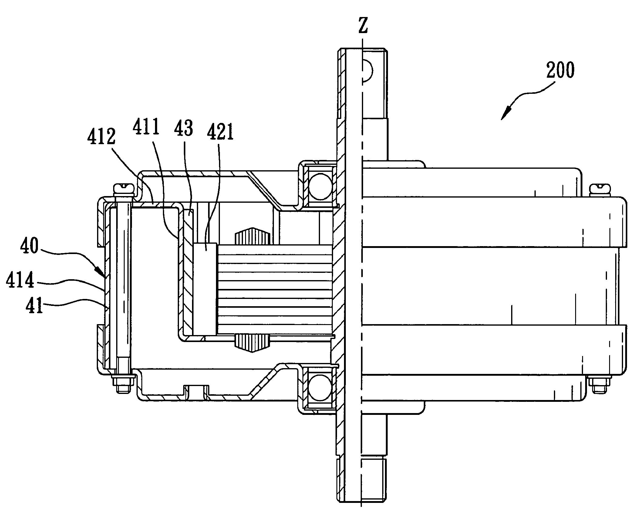
[0016]Referring to FIGS. 3 and 4, the first preferred embodiment of a ceiling fan motor 200 according to the present invention is shown to comprise a housing 20, a stator 30, and a rotor unit 40.

[0017]The housing 20 includes top and bottom casing parts 21, 22.

[0018]The stator 30 is disposed in the housing 20 between the top and bottom casing parts 21, 22, and has a stator axis (Z).

[0019]The rotor unit 40 includes a mounting seat 41 connected to the housing 20 and surrounding the stator 30, and a rotor 42 disposed on the mounting seat 41 adjacent to the stator 30.

[0020]The mounting seat 41 includes an inner tubular wall 411 surrounding the stator 30, an outer tubular wall 414 spaced apart from and surrounding the inner tubular wall 411, an intermediate web 412 interconnecting top ends of the inner and outer tubul...


PUM


Abstract

A ceiling fan motor includes a housing having top and bottom casing parts, a stator disposed in the housing and having a stator axis, and a rotor unit including a mounting seat that has an inner tubular wall surrounding the stator, an outer tubular wall spaced apart from and surrounding the inner tubular wall, and an intermediate web interconnecting the inner and outer tubular walls. The outer tubular wall is connected between the top and bottom casing parts. The rotor unit further includes a rotor supported by the inner tubular wall. The top and bottom casing parts have peripheral ends respectively overlapping top and bottom ends of the outer tubular wall.

Description

CROSS-REFERENCE TO RELATED APPLICATION[0001]This application claims priority of Taiwanese Application No. 095218953, filed on Oct. 26, 2006.BACKGROUND OF THE INVENTION[0002]1. Field of the Invention[0003]The invention relates to a motor, more particularly to a ceiling fan motor.[0004]2. Description of the Related Art[0005]Referring to FIGS. 1 and 2, a conventional ceiling fan motor 100 includes a motor housing having top and bottom casing parts 11, 12, a stator 13 disposed between the top and bottom casing parts 11, 12, and a rotor 14 connected to the top and bottom casing parts 11, 12 and surrounding the stator 13. When choosing the size of the stator 13 and the rotor 14, reference must be made to the standard specifications of the top and bottom casing parts 11, 12. Since such standard specifications of the top and bottom casing parts 11, 12 are not suitable for small motors, the stator 13 and the rotor 14 of the conventional ceiling fan motor 100 necessarily must be made having l...

Claims


Application Information

Patent Timeline
Patent Type & Authority Patents(United States)
IPC IPC(8): H01K5/00
CPCF04D25/088H02K5/04H02K1/2786H02K1/2791
Inventor YAO, CHAO-CHIN
Owner YAO CHAO CHIN
Why Eureka
Try Eureka