Height-adjustable intervertebrae implant

a technology of height adjustment and intervertebral implants, which is applied in the field of height adjustment of intervertebral implants, can solve the problem that the height adjustment of known intervertebral implants cannot be achieved

Active Publication Date: 2009-11-17
BIEDERMANN TECH GMBH & CO KG
View PDF30 Cites 208 Cited by
  • Summary
  • Abstract
  • Description
  • Claims
  • Application Information

AI Technical Summary

Benefits of technology

[0022]Use of an intervertebral implant in accordance with the present invention can enable one to alter the height (or thickness) of the implant in its assembled state by shifting the first part and the second part relative to each other by means of the contact surfaces moving relative to each other. The motion of the first part and the second part relative to each other, preferably proceeding in an arcuate path such as a screw or helical motion, is particularly well-suited for the use of the intervertebral implant in minimally-invasive applications.
[0024]In other preferred embodiments, a self-locking mechanism such as, for example, roughened or stepped contact surfaces, are provided, which prevents the inadvertent shifting of the first part and the second part relative to each other.

Problems solved by technology

However, this known intervertebral implant is not height-adjustable.

Method used


Image

  • Height-adjustable intervertebrae implant
  • Height-adjustable intervertebrae implant
  • Height-adjustable intervertebrae implant

Examples


Embodiment Construction

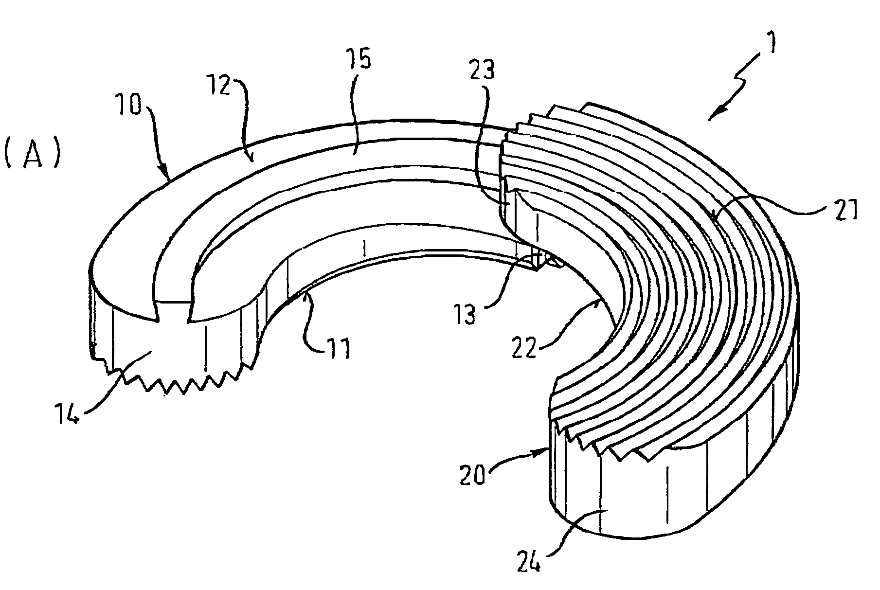
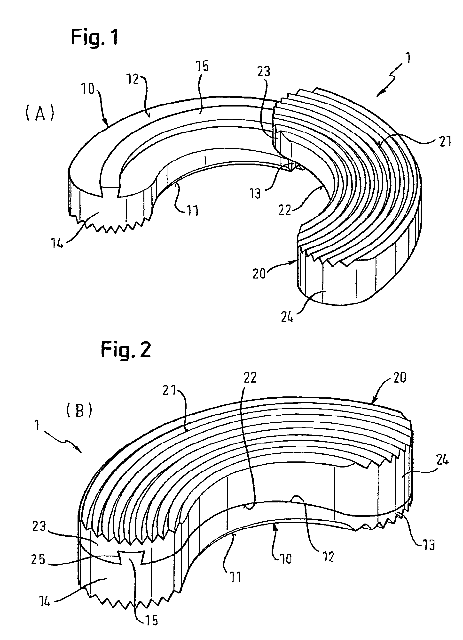
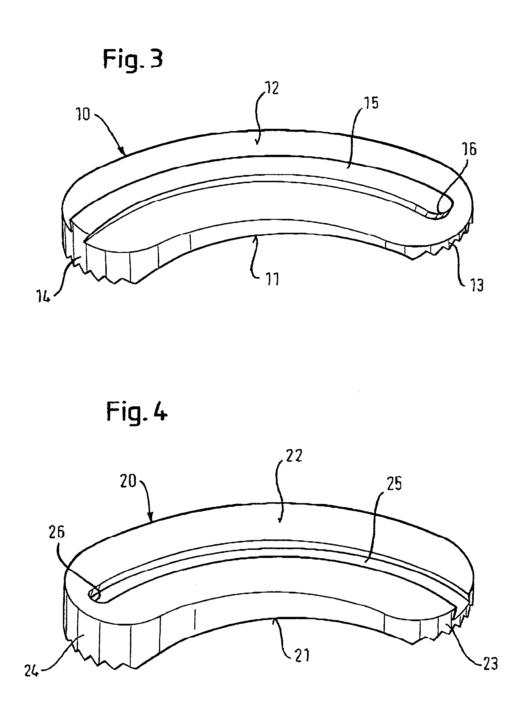
[0037]An intervertebral implant according to one embodiment of the present invention is illustrated with reference to FIGS. 1 to 6. As is evident from FIG. 1 and FIG. 2, intervertebral implant 1 consists of two curved parts 10, 20, which are provided to be in the shape of an arc, curve or segment of a helix in this particular embodiment.

[0038]As is best seen in FIG. 6, the two parts 10, 20 are provided as wedge-like sections with opposite tapers, each of which has a thick end 14, 24 that forms a base end of the wedge and a tapered end 13, 23 opposite to the thick end. In this arrangement, the two parts 10, 20 can be connected together by contacting each other at their wedge surfaces 12, 22 using the guide surfaces provided by ridge 15 and groove 25. Thus, reference generally will be made to these wedge surfaces as “contact surfaces”12, 22, hereinafter. Thus, seen from an elevational view (such as FIG. 6), when the two parts are fully engaged, intervertebral implant 1 is approximatel...


PUM


Abstract

An intervertebral implant for insertion between two vertebrae is disclosed. A first part has a first contact surface extending between its two ends a first guide surface extending out from the first contact surface. A second part has a second contact surface extending between its ends, and a second guide surface recessed into the second contact surface. The first guide surface and the second guide surface cooperate so that the first contact surface of the first part can slide relative to the second contact surface of the second part with a translation motion guided by the cooperating structures of the first and second guide surfaces. The height of the intervertebral implant can be altered by shifting the first part and the second part relative to each other by moving the contact surfaces relative to each other by using the cooperating guide surfaces.

Description

CROSS REFERENCE TO RELATED APPLICATIONS[0001]This application claims priority from U.S. Provisional Application Ser. No. 60 / 528,412 filed Dec. 9, 2003.FIELD OF THE INVENTION[0002]The present invention relates to intervertebral implants, particularly, to height-adjustable intervertebral implants.BACKGROUND OF THE INVENTION[0003]Intervertebral implants are employed generally after the removal of an intervertebral disc in order to stabilize the space between the vertebrae.[0004]An intervertebral implant is described in EP 0 977 529 B1. The implant is shaped essentially like a rectangular parallelepiped and comprises two side walls, one front wall, and one back wall. The bottom surface and the top surface are open. The hollow space of the intervertebral implant enclosed by the four walls contains at least one movable element with a surface facing towards the top surface or bottom surface, and one adjustment element that is supported in the front wall and back wall, allowing the movable ...

Claims


Application Information

Patent Timeline
Patent Type & Authority Patents(United States)
IPC IPC(8): A61F2/44A61B17/70A61B17/56A61F2/00A61F2/02A61F2/30
CPCA61F2/442A61F2/30965A61F2310/00023A61F2/4465A61F2002/30131A61F2002/30308A61F2002/30387A61F2002/304A61F2002/3055A61F2002/30556A61F2002/30604A61F2002/30785A61F2002/30879A61F2002/30892A61F2002/30904A61F2220/0025A61F2230/0013A61F2230/0063A61F2250/0009A61B17/70
Inventor BIEDERMANN, LUTZMATTHIS, WILFRIED
Owner BIEDERMANN TECH GMBH & CO KG
Why Eureka
Try Eureka