Disinfection cabinet drawer life test machine

A life test and disinfection cabinet technology, which is applied to the testing of machines/structural components, measuring devices, instruments, etc., can solve the problems of no equipment, etc., and achieve the effects of reducing errors, accurate counting, and uniform push-pull force

Inactive Publication Date: 2007-07-11
陈柯杰
View PDF0 Cites 16 Cited by
  • Summary
  • Abstract
  • Description
  • Claims
  • Application Information

AI Technical Summary

Problems solved by technology

But there is no such device yet

Method used


Image

  • Disinfection cabinet drawer life test machine
  • Disinfection cabinet drawer life test machine
  • Disinfection cabinet drawer life test machine

Examples


Embodiment Construction

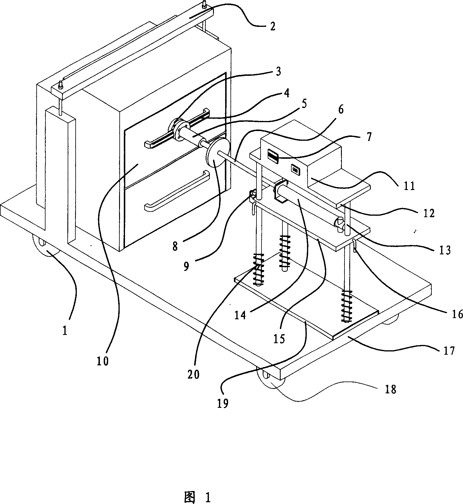
[0036] The present invention is described in detail below in conjunction with accompanying drawing:

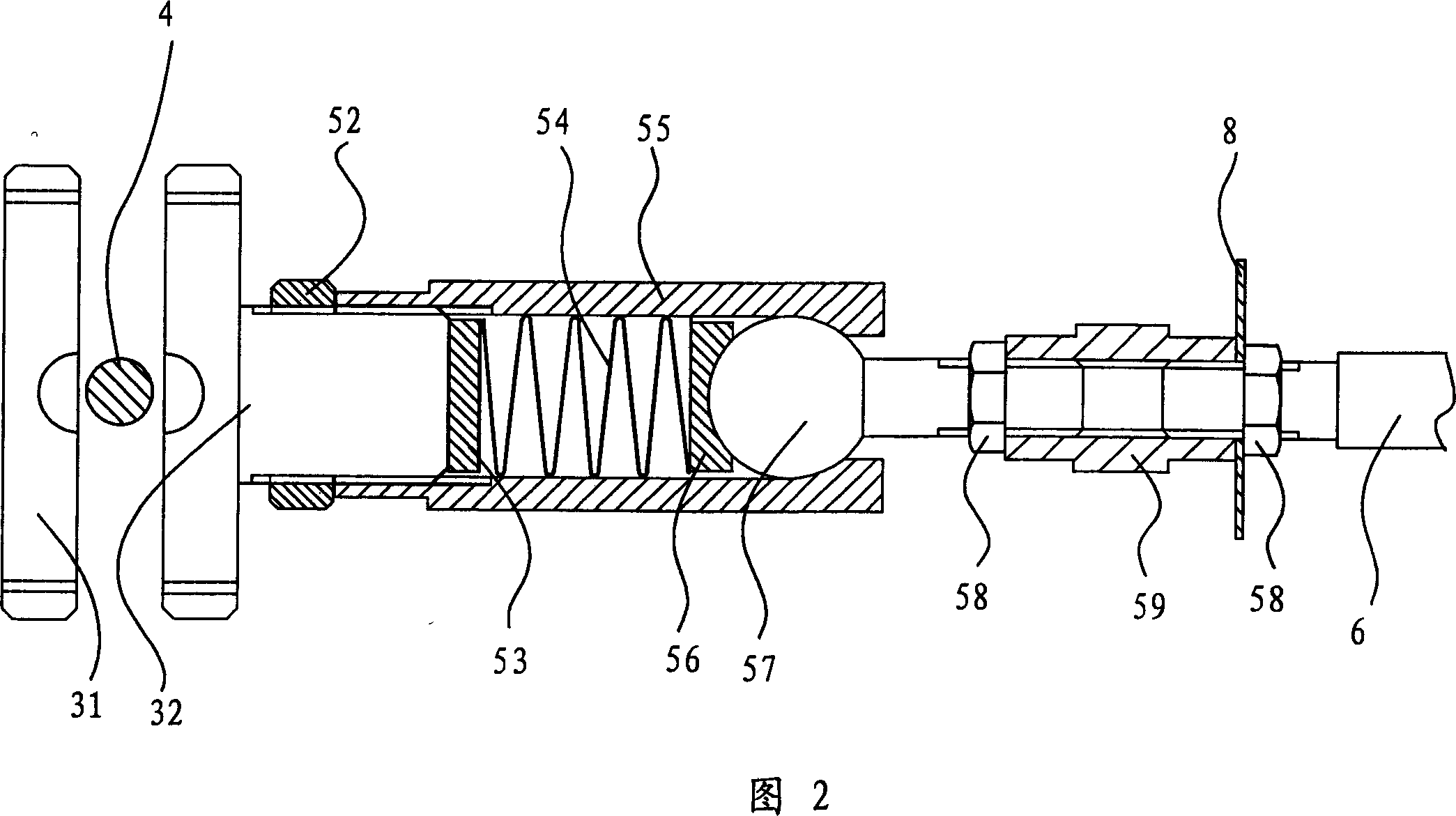
[0037] The disinfection cabinet drawer life tester of the present invention comprises an automatic push-pull device, a counter 7 and a clamp 3, one end of the clamp 3 is detachably connected to the drawer handle 4 of the disinfection cabinet, the other end of the clamp 3 is connected to the automatic push-pull device, and the automatic push-pull device is connected to the counter 7 connections. When the life test of the disinfection cabinet drawer 10 is required, the fixture 3 and the disinfection cabinet drawer 10 are fixedly connected together, please refer to FIG. 31 center positions are provided with arc-shaped depressions, when in use, the chuck bolts 32 are fastened with the movable fixture piece 31, the disinfection cabinet drawer handle 4 is located in the arc-shaped depressions of the chuck bolts 32 and the movable fixture piece 31, and the chuck bolts 32 has a throu...


PUM


Abstract

The invention relates to a disinfection cabinet drawer endurance tester. It comprises fixture, automatic push-pull unit, calculator, with the said fixture detachably connected with the handle of the disinfection cabinet drawer, the fixture connected with the automatic push-pull device, and the calculator connected with the automatic push-pull device. It is simple, with automatic push and pull of the drawer, precise calculation, saving man power, and improved in testing efficiency and accuracy.

Description

technology field, [0001] The invention relates to a lifespan, in particular to a life tester for a disinfection cabinet drawer. Background technique [0002] Most of the early disinfection cabinet products were wall-mounted, but now most of these wall-mounted disinfection cabinet products are replaced by floor-standing embedded disinfection cabinets. To improve the quality of disinfection cabinet products, in addition to various disinfection technical indicators, One of the most important factors is whether the drawer action life of the disinfection cabinet meets the standard. In order to know whether the number of drawer actions has reached the design index after the product sample, it is necessary to randomly check whether the disinfection cabinet deviates from the drawer action life index during the production process. Carry out the life test of the drawer action. At present, this kind of test is relatively primitive and manual. The work of the tester is relatively boring...

Claims


Application Information

Patent Timeline
Patent Type & Authority Applications(China)
IPC IPC(8): G01M19/00G01M99/00
Inventor 陈明陈柯杰
Owner 陈柯杰
Why Eureka
Try Eureka