Thermal barrier coating material

a technology of thermal barrier coating and coating material, which is applied in the direction of niobium compounds, machines/engines, continuous combustion chambers, etc., can solve the problems of actual remaining tensile stress between the coating and the substrate metal part, monoclinic phase progressively precipitating, and inability to use pure zirconia as a high temperature structure material, etc., to achieve high melting point, low thermal conductivity, and large thermal expansivity

Active Publication Date: 2009-11-24
MITSUBISHI HEAVY IND LTD
View PDF24 Cites 3 Cited by
  • Summary
  • Abstract
  • Description
  • Claims
  • Application Information

AI Technical Summary

Benefits of technology

These materials provide enhanced thermal insulation, reduced thermal conductivity, and improved peeling resistance, enabling longer-lasting heat resistance and efficient operation in high-temperature applications like gas turbines.

Problems solved by technology

and the volume of pure zirconia itself changes acutely as its temperature rises or drops, with the result that it is destroyed in the phase transition between monoclinic and tetragonal phases, so that pure zirconia cannot be used as a material for high temperature structure.
It has been reported that even for partially stabilized zirconia, for which the amount of stabilizing agent is controlled in order to stabilize the tetragonal phase, a monoclinic phase progressively precipitates when used for a long period of time at a high temperature and in a heat cycle where the temperature is repeatedly increased and decreased, and this has been an important problem in using zirconia as a thermal barrier coating.
However, there is a problem of an actual remaining tensile stress between the coating and the substrate metal part, since the thermal expansion coefficient of La2Zr2O7 is smaller than that of zirconia.

Method used

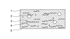

Image

  • Thermal barrier coating material
  • Thermal barrier coating material
  • Thermal barrier coating material

Examples


example 1

[0048]It is known that various kinds of physical property values at a nanometer scale can be obtained by changing conditions for solving a primitive equation in quantum mechanics. This method is a research method that performs an ab initio calculation, which does not use experimental results as a parameter, to obtain the information sought, and it is known as a “first principle calculation”. In the present invention, this first principle calculation is used in order to estimate the thermal expansion coefficient α and the thermal conductivity λ from a crystal structure.

[0049](Reference: “Science & Technology Trends”, December issue 2001, “http: / / www.nistep.go.jp / achiev / ftx / jpn / stfc / stt009j / feature3.html#4-0”, Ministry of Education, Culture, Sports, Science and Technology Japan, National Institute of Science and Technology Policy, Science and Technology Foresight Center).

[0050]First, the present inventors examined the thermal expansion coefficient α and the thermal conductivity λ that...

example 2

[0061]In the present example, the combining of the materials for which the thermal expansion coefficients and thermal conductivities were measured in the above example 1 was examined.

[0062]According to example 1, since the thermal expansion coefficients of La2Si2O7, La2Ti2O7, Sr2Ta2O7 and LaTaO4 are smaller than that of zirconia as they are, when they are used as materials for a thermal barrier coating, there is a possibility of tensile stress occurring. Consequently, in order to achieve high thermal expansion coefficients while maintaining the low thermal conductivities of these materials, the combining of these materials with other materials that have high thermal expansion coefficients shown in Table 1 was examined.

[0063]When combining two kinds of ceramics having a large difference between their thermal expansion coefficients, the thermal expansion coefficient of the combined material (αc) is expressed by the following expression (3), known as Turner's expression. In expression ...

example 3

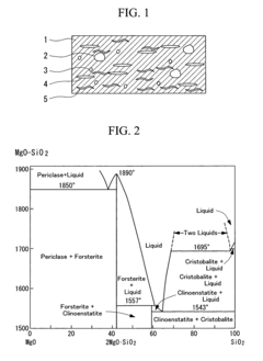
[0072]Mg2SiO4 is used as an insulation material for electronic / electrical devices such as IC substrates and packages. However, it has not been used for a high temperature structure material such as a thermal barrier coating. The present inventors focused on the high thermal expansion property and low thermal conductivity of Mg2SiO4, and considered its application for a thermal barrier coating. First, Mg2SiO4 and similar compounds were investigated.

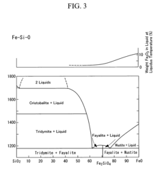
[0073]Mg2SiO4 is known by the mineral name, Forsterite, and belongs to the materials which are categorized as orthorhombic and space group Pmnb, and have an olivine type structure of M2SiO4 (M is a divalent metal element). As other materials that are categorized as orthorhombic and space group Pmnb, and have an olivine type structure, there are Fe2SiO4 (Fayalite), Mn2SiO4 (Tephroite), Ni2SiO4 (Liebenbergite), Co2SiO4, and the like.

[0074]The divalent metal element expressed by the above composition formulas by M does not have to be one kind...


PUM

PropertyMeasurementUnit
surface temperatureaaaaaaaaaa
temperatureaaaaaaaaaa

Abstract

There is provided a novel thermal barrier coating material which does not have a problem of phase transition, whose melting point is higher than its working temperature range, whose thermal conductivity is smaller than that of zirconia, and whose thermal expansion coefficient is greater than that of zirconia. The thermal barrier coating material comprises as a main component, a composition having an orthorhombic or monoclinic structure derived from perovskite (for example, a tabular perovskite structure expressed by the composition formula A2B2O7), or a tetragonal layer structure having a c axis / a axis ratio equal to or greater than 3 (for example, a K2NiF4 structure, a Sr3Ti2O7 structure, or a Sr4Ti3O10 structure), a composition expressed by the composition formula LaTaO4, or a composition having an olivine type structure expressed by the composition formula M2SiO4 or (MM′)2SiO4 (where M, M′ are divalent metal elements).

Description

TECHNICAL FIELD[0001]The present invention relates to a thermal barrier coating material applicable to equipment parts used in a high temperature environment such as of a rotor blade of a gas turbine for power generation, a stator blade, a combustor, and a jet engine.BACKGROUND ART[0002]In order to increase the efficiency of gas turbines, jet engines, and the like, the temperature of the combustion gas continues to be increased. As a result, in order to protect metal parts from the high temperature (for example, blade surface temperature of a 1500° C. class gas turbine reaches approximately 1400° C.), a thermal barrier coating (TBC) is coated on the surface of the parts. As a material for this thermal barrier coating, ceramic having a low thermal conductivity such as rare earth stabilized zirconia is used (for example, refer to Japanese Unexamined Patent Applications, First Publications No. Hei 08-074505, and No. Hei 10-183013). The above thermal barrier coating is applied by means ...

Claims


Application Information

Patent Timeline
Patent Type & AuthorityPatents(United States)
IPC IPC(8): C04B35/101C23C4/10C01B13/14C01G23/00C01G35/00C01G53/00C04B35/16C04B35/20C04B35/22C04B35/462C04B35/47C04B35/495C09D1/00C23C4/11C23C28/00C23C30/00F01D5/28F02C7/00F23R3/42
CPCC04B35/01C04B35/18C04B35/20C04B35/22C04B35/462C04B35/47C04B35/495C23C4/105C23C30/00F01D5/288C04B35/16Y02T50/672C04B2235/3205C04B2235/3206C04B2235/3208C04B2235/3213C04B2235/3215C04B2235/3224C04B2235/3225C04B2235/3227C04B2235/3229C04B2235/3232C04B2235/3239C04B2235/3241C04B2235/3244C04B2235/3251C04B2235/3255C04B2235/3258C04B2235/3272C04B2235/3275C04B2235/3279C04B2235/3286C04B2235/3289C04B2235/656C04B2235/76C04B2235/77C04B2235/80C04B2235/81C04B2235/9607Y02T50/67C23C4/11Y02T50/60
InventorAKIYAMA, KATSUNORINAGANO, ICHIROSHIDA, MASATOOTA, SATOSHI
OwnerMITSUBISHI HEAVY IND LTD