Kinetic energy rod warhead with projectile spacing

a technology of kinetic energy rods and projectiles, which is applied in the direction of projectiles, ammunition projectiles, weapons, etc., can solve the problems of not being able to reach, not always effective at destroying targets, and heavy casualties, so as to improve the chance of destroying targets and increase the ability to penetrate targets

Inactive Publication Date: 2009-12-01
RAYTHEON CO
View PDF142 Cites 5 Cited by
  • Summary
  • Abstract
  • Description
  • Claims
  • Application Information

AI Technical Summary

Benefits of technology

[0010]It is a further object of this invention to provide a kinetic energy rod warhead with increased ability to penetrate a target.
[0011]It is a further object of this invention to provide a kinetic energy rod warhead which has a better chance of destroying a target.
[0013]The subject invention results from the realization that a higher lethality kinetic energy rod warhead can be achieved in a warhead with separate projectile rod bays, each bay including rods having their own distinct drag properties thus enhancing the temporal and / or spatial separation of the rods and the overall destructive capability of the kinetic energy rod warhead.

Problems solved by technology

Moreover, biological warfare bomblets and chemical warfare submunition payloads are carried by some “hit-to-kill” threats and one or more of these bomblets or chemical submunition payloads can survive and cause heavy casualties even if the “hit-to-kill” vehicle accurately strikes the target.
Blast fragmentation type warheads, unlike “hit-to-kill” vehicles, are not navigable.
The fragments, however, are not always effective at destroying the target and, again, biological bomblets and / or chemical submunition payloads survive and cause heavy casualties.
Some of the rods may miss the target, others may not penetrate the target, and even those that hit and penetrate the target may not be sufficient to effectively destroy the target.
Moreover, it may not be feasible or possible to address a single target with multiple warheads each carried by a single missile.

Method used


Image

  • Kinetic energy rod warhead with projectile spacing
  • Kinetic energy rod warhead with projectile spacing
  • Kinetic energy rod warhead with projectile spacing

Examples


Embodiment Construction

[0029]Aside from the preferred embodiment or embodiments disclosed below, this invention is capable of other embodiments and of being practiced or being carried out in various ways. Thus, it is to be understood that the invention is not limited in its application to the details of construction and the arrangements of components set forth in the following description or illustrated in the drawings. If only one embodiment is described herein, the claims hereof are not to be limited to that embodiment. Moreover, the claims hereof are not to be read restrictively unless there is clear and convincing evidence manifesting a certain exclusion, restriction, or disclaimer.

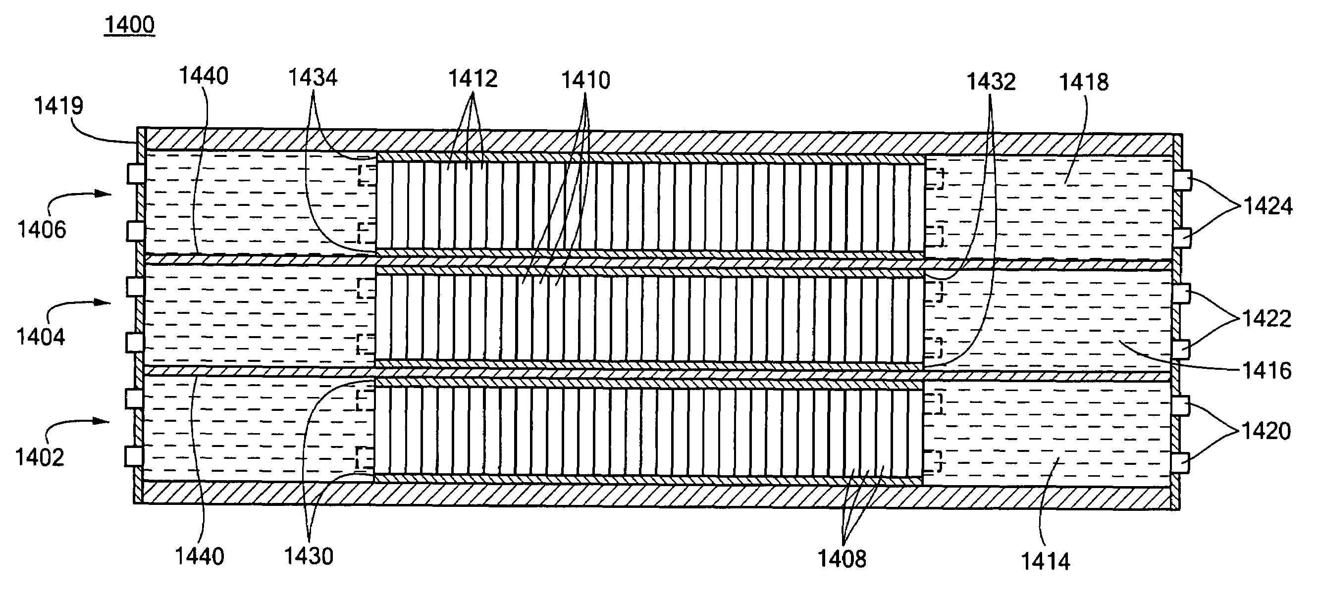
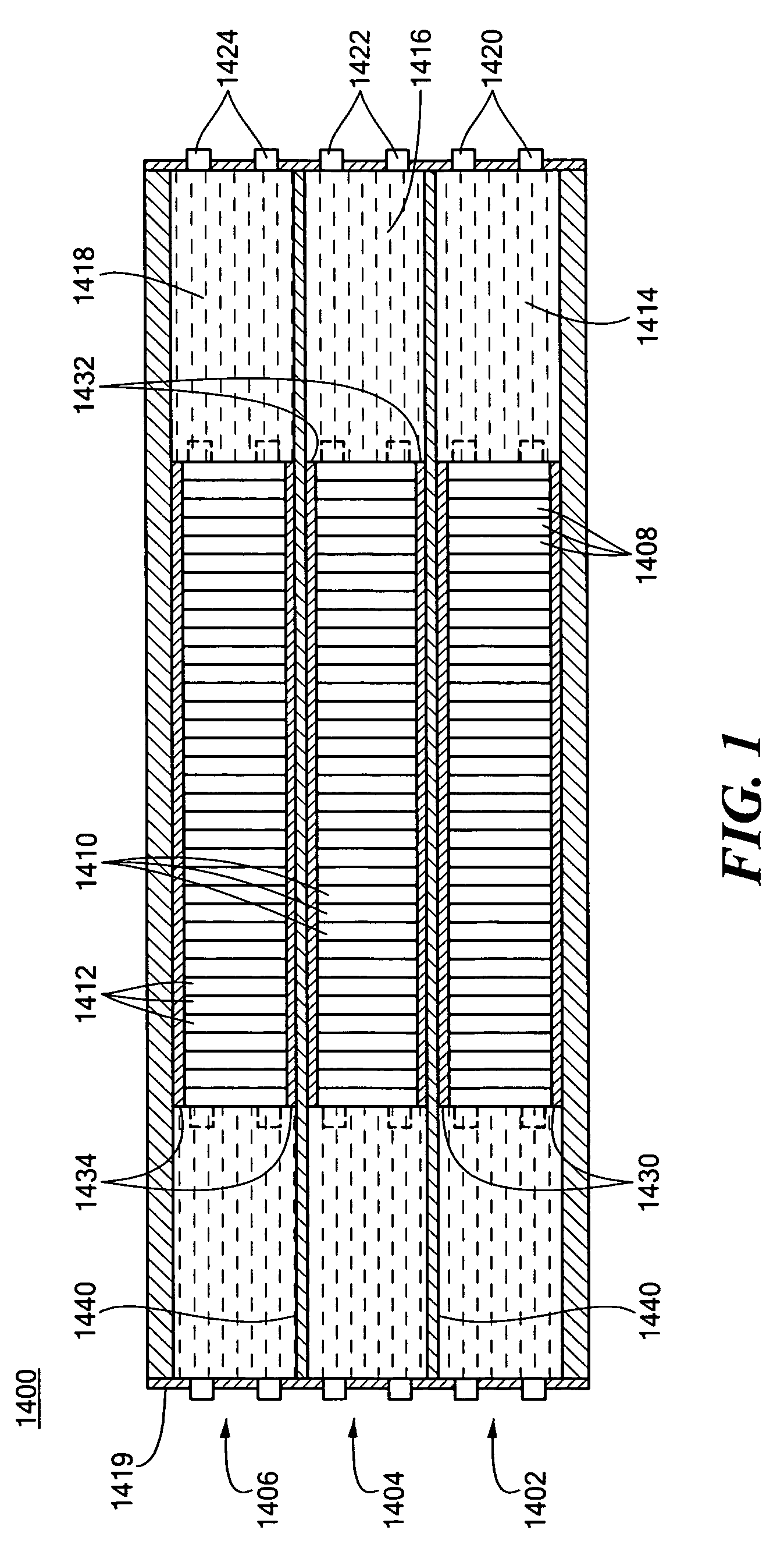
[0030]Previous kinetic energy rod warhead designs deploy a single set of rod projectiles or penetrators towards a target. Aiming and aligning techniques and structures may be employed to improve accuracy, and different sized or shaped rods may be utilized for greater target effect, depending on a particular desired applicat...


PUM


Abstract

A kinetic energy rod warhead bay configuration includes a plurality of bays. Each bay includes a plurality of rods, an explosive for deploying the rods, and a detonator for detonating the explosive. One bay is structured and arranged as a first bay. One bay is structured and arranged as a last bay with rods configured to have more drag than the rods of the first bay. At least one other bay is structured and arranged as an intermediate bay. The rods of the intermediate bay are configured to have more drag than the rods of the first bay but less drag than the rods of the last bay to space apart the rod sets of the bays upon deployment.

Description

RELATED APPLICATIONS[0001]This application is a Continuation-in-Part of prior U.S. patent application Ser. No. 11 / 059,891 filed Feb. 17, 2005 and this application is a Continuation-in-Part of prior U.S. patent application Ser. No. 11 / 060,179 filed Feb. 17, 2005, and the latter applications are each a Continuation-in-Part application of prior U.S. patent application Ser. No. 10 / 924,104 filed Aug. 23, 2004 now abandoned and a Continuation-in-Part application of prior U.S. patent application Ser. No. 10 / 938,355 filed Sep. 10, 2004, and each of these latter two applications are a Continuation-in-Part of prior U.S. patent application Ser. No. 10 / 456,777, filed Jun. 6, 2003 now U.S. Pat. No. 6,910,423 which is a Continuation-in-Part of prior U.S. patent application Ser. No. 09 / 938,022 filed Aug. 23, 2001, issued on Jul. 29, 2003 as U.S. Pat. No. 6,598,534B2. All of these patent applications and patents are incorporated herein by reference.FIELD OF THE INVENTION[0002]This subject invention...

Claims


Application Information

Patent Timeline
Patent Type & Authority Patents(United States)
IPC IPC(8): F42B12/32
CPCF42B12/64F42B12/60
Inventor LLOYD, RICHARD M.
Owner RAYTHEON CO
Why Eureka
Try Eureka