Rotary cutting tool assembly and cutting insert and tool shank therefor

Active Publication Date: 2009-12-01
KENNAMETAL INC
View PDF14 Cites 86 Cited by
  • Summary
  • Abstract
  • Description
  • Claims
  • Application Information

AI Technical Summary

Problems solved by technology

For relatively large drilling tools, however, a drill made entirely of such abrasion-resistant materials is generally too expensive, and is not economical in spite of its excellent cutting performance.
The disadvantage of these tools, however, is that they can be repointed only to a limited extent.
Suc

Method used


Image

  • Rotary cutting tool assembly and cutting insert and tool shank therefor
  • Rotary cutting tool assembly and cutting insert and tool shank therefor
  • Rotary cutting tool assembly and cutting insert and tool shank therefor

Examples


Embodiment Construction

[0025]Directional phrases used herein, such as, for example, left, right, front, back, top, bottom and derivatives thereof, relate to the orientation of the elements shown in the drawings and are not limiting upon the claims unless expressly recited therein. Identical parts are provided with the same reference number in all drawings.

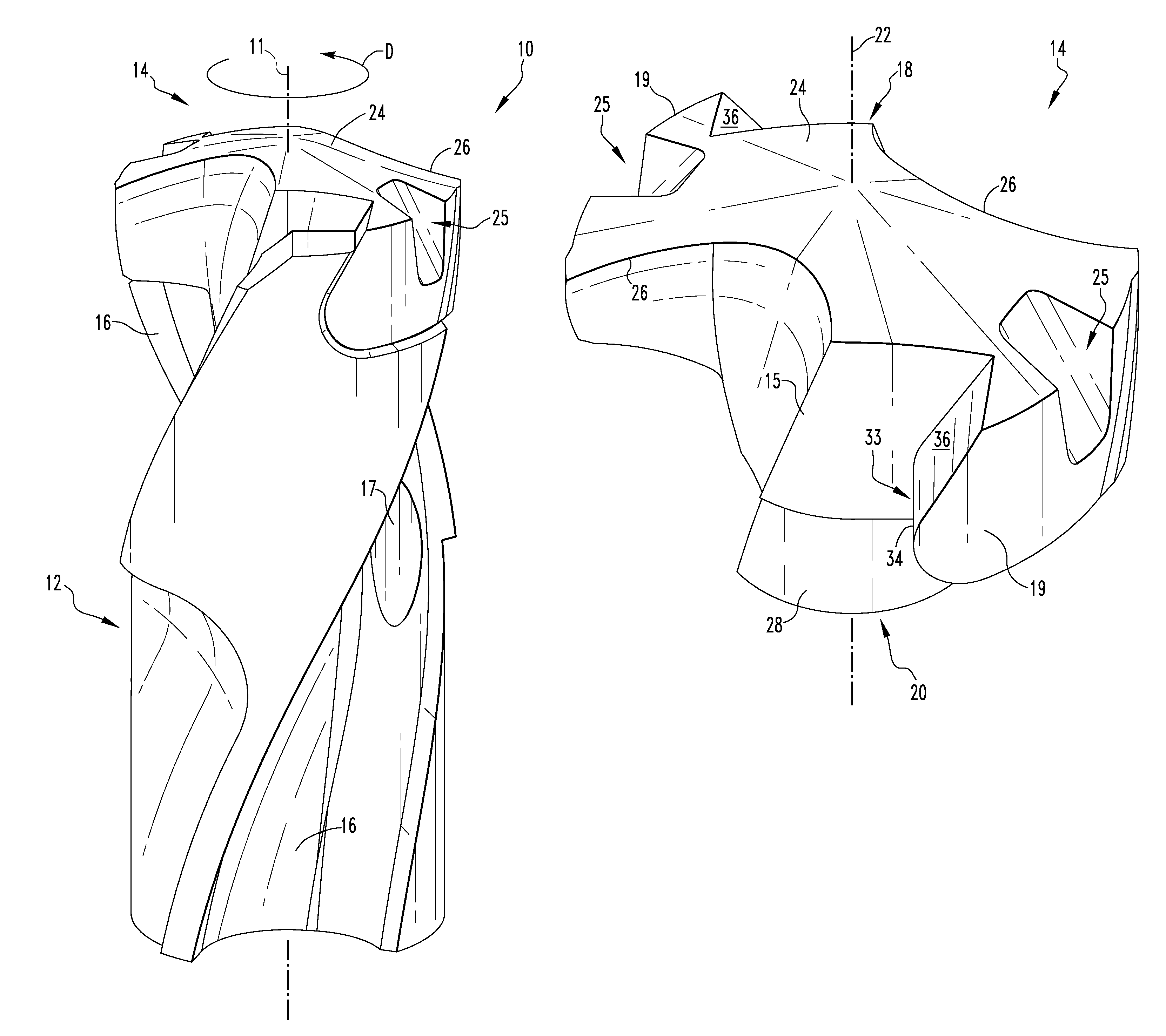
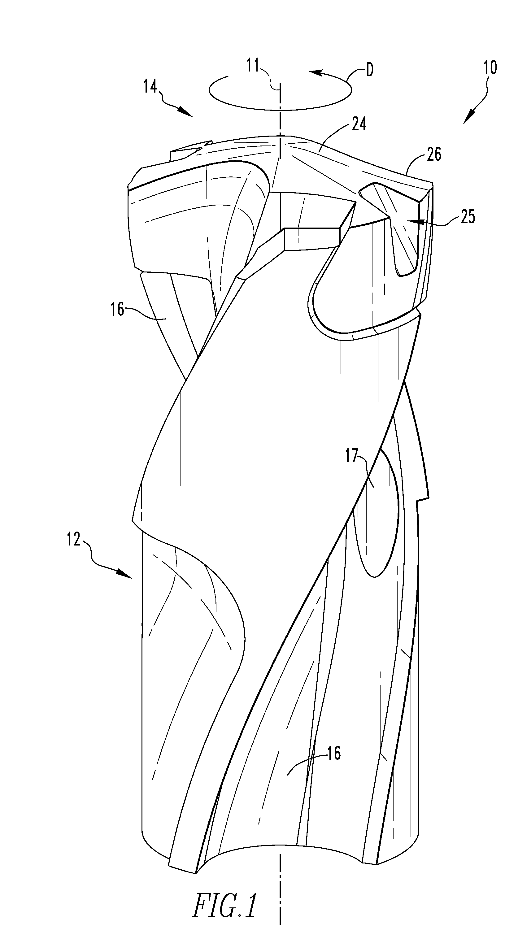
[0026]FIG. 1 shows an example of a cutting tool assembly 10, in accordance with one non-limiting embodiment of the invention, for conducting rotary cutting operations on a work piece (not shown) when tool assembly 10 is rotated about a central longitudinal axis 11 in a direction D. A recessing, milling or reaming tool, for example, may be similarly configured. The cutting tool assembly 10 includes a shank 12 and a replaceable cutting insert 14 which is installed on, and engages the tool shank 12. Cutting tool assembly 10 is a modular drill which is preferably of the so-called twist drill type, having helical flutes 16 disposed along the sides of the cutt...


PUM

PropertyMeasurementUnit
Angleaaaaaaaaaa
Angleaaaaaaaaaa
Angleaaaaaaaaaa

Abstract

A tool shank and a replaceable cutting insert are provided for a rotary cutting tool assembly. The tool shank has a drive surface including a central portion, a first portion of generally planar shape extending away from the central portion and a second portion of generally planar shape extending away from the central portion in a direction generally transverse to a central axis of the tool shank. The replaceable cutting insert has a driven surface including another central portion, a first portion of generally planar shape extending away from the other central portion and a second portion of generally planar shape extending away from the other central portion in a direction generally transverse to a central axis of the insert. The central portion of the driven surface has a curved surface transitioning between the first portion and the second portion of the driven surface. A portion of the driven surface of the replaceable cutting insert is engaged by a corresponding portion of the drive surface of the tool shank.

Description

BACKGROUND[0001]1. Field of the Invention[0002]The invention relates generally to rotary cutting tools and, more particularly, to drilling tools with a replaceable cutting insert. The invention also relates to cutting inserts and tool shanks for rotary cutting tools.[0003]2. Background Information[0004]The modern metalworking trade primarily uses twist drills to make borings. Depending on the application, these twist drills can differ in terms of their cutting material and geometry. Cutting materials traditionally used are increasingly being replaced by different types of cutting materials that have significantly higher resistance to abrasion. For relatively large drilling tools, however, a drill made entirely of such abrasion-resistant materials is generally too expensive, and is not economical in spite of its excellent cutting performance. Alternatives are twist drills in which a drill tip made of abrasion-resistant materials is permanently attached to a carrier tool that is gener...

Claims


Application Information

Patent Timeline
IPC IPC(8): B23B51/02B23B51/06
CPCB23B51/02B23B51/06B23B2205/02B23B2251/02B23B2251/50Y10T407/23B23B2260/078Y10S408/713Y10T407/1908Y10T408/909Y10T407/1906B23B2260/072
Inventor RUY FROTA DE SOUZA, FILHO
Owner KENNAMETAL INC
Why Eureka
Try Eureka