Safety switch

a safety switch and switch technology, applied in the field of safety switches, can solve the problems of circuit being cut off frequently, burning of the circuit,

Active Publication Date: 2009-12-01
HUANG ALBERT
View PDF32 Cites 13 Cited by
  • Summary
  • Abstract
  • Description
  • Claims
  • Application Information

AI Technical Summary

Benefits of technology

[0008]The primary objective of the present invention is to provide a safety switch that prevents a circuit from being switched between on and off states unexpectedly.

Problems solved by technology

If the switch is too loose to be turned between on and off, the bimetal strip might be bent easily when being heated and cause the circuit being cut off frequently.
Moreover, the bent heated bimetal strip might recover to be straight easily and turn on the switch unexpectedly after the temperature lowers, such that might lead to burning of the circuit.

Method used


Image

  • Safety switch
  • Safety switch
  • Safety switch

Examples


Embodiment Construction

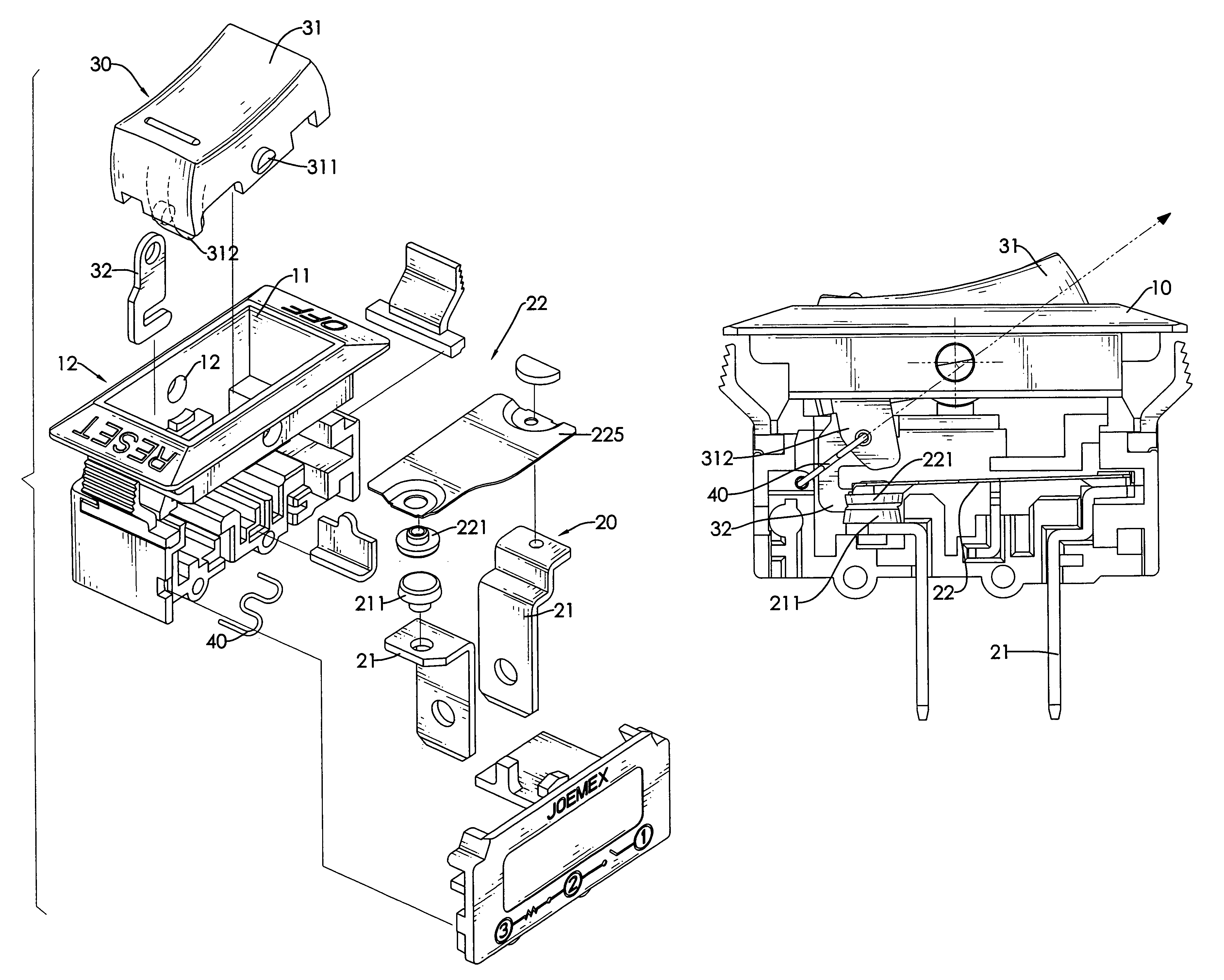
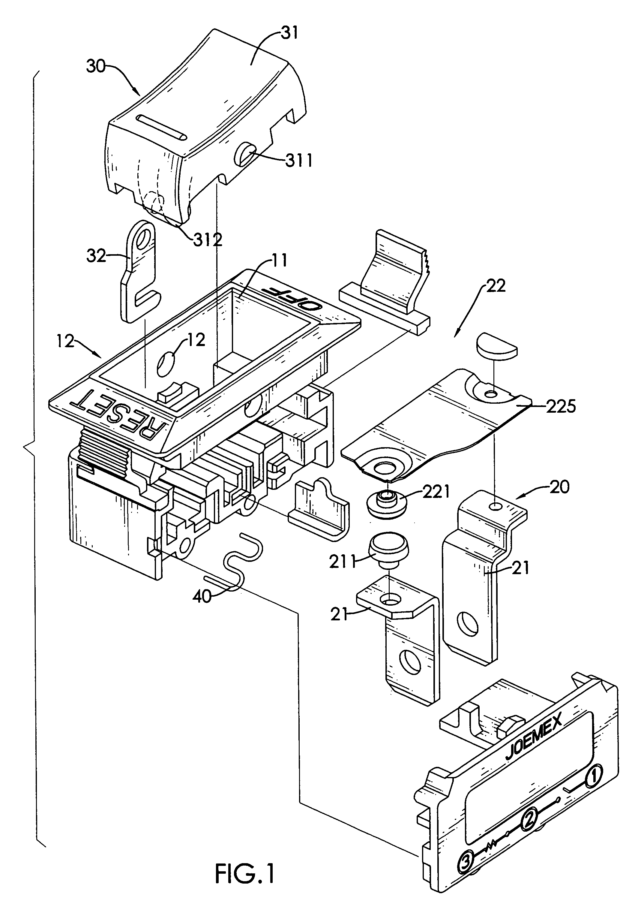
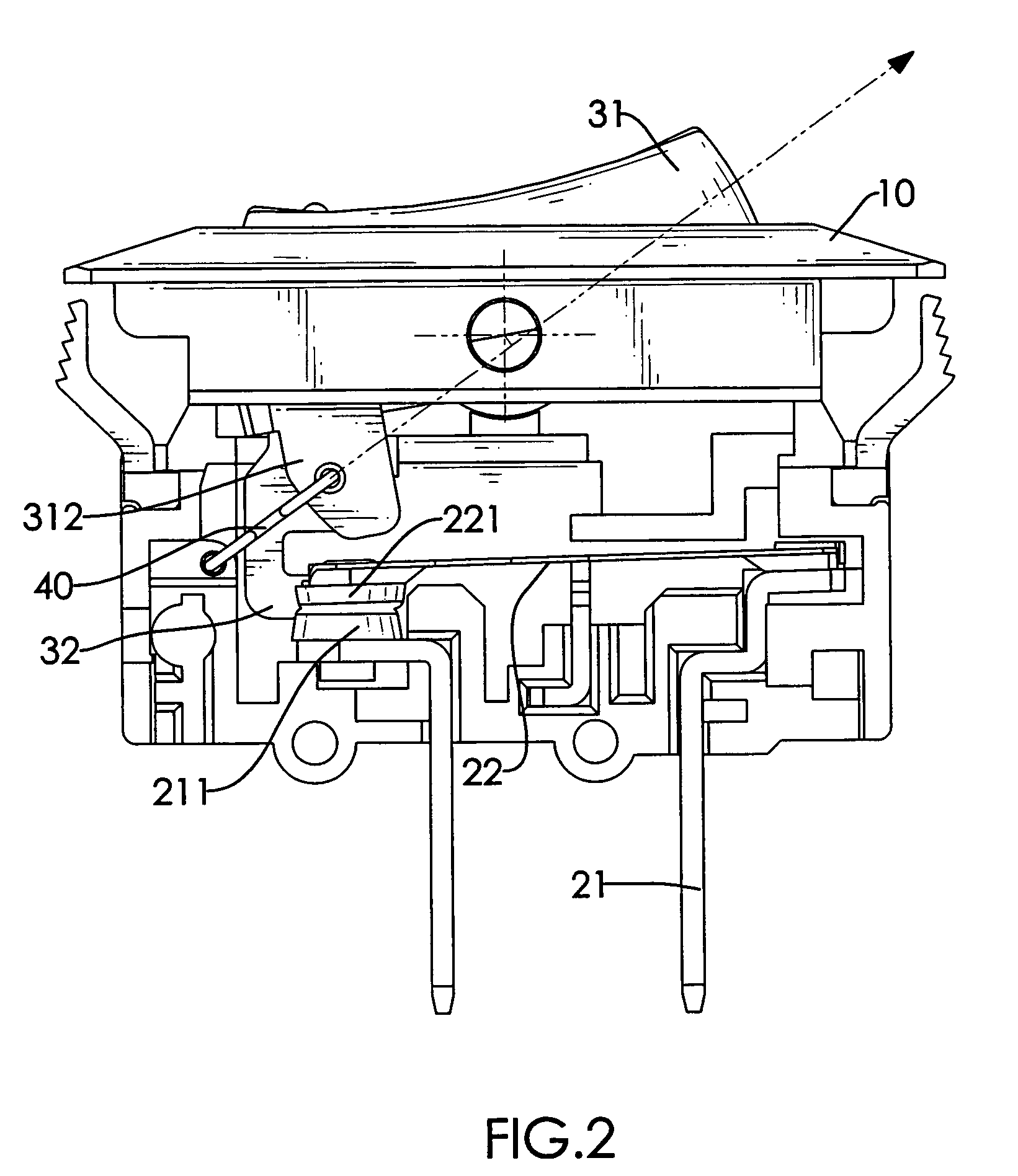
[0014]With reference to FIGS. 1 and 2, a safety switch in accordance with the present invention comprises a housing (10), a conducting assembly (20), a switching assembly (30) and a resilient member (40).

[0015]The housing (10) is hollow and has a top, a bottom, an on-end, an off-end, two side surfaces, an opening (11) and two optional pivot holes.

[0016]The opening (11) is formed through the top of the housing (10).

[0017]The pivot holes (12) are formed respectively through the side surfaces of the housing (10).

[0018]The conducting assembly (20) has two conductors (21) and a bimetal strip (22).

[0019]The conductors (21) are mounted through the bottom of the housing (10) respectively near the on-end and the off-end and protrude out of the bottom of the housing (10) to attach respectively to two separated ends of a circuit. Each conductor (21) has an inner end and the conductor (21) near the on-end of the housing (10) may have a conducting head (211).

[0020]The conducting head (211) is mo...


PUM


Abstract

A safety switch has a housing, a conducting assembly, a switching assembly and a resilient member. The housing has an on-end and an off-end. The conducting assembly is mounted in the housing and has two conductors and a bimetal strip. The conductors respectively correspond to the on and off-ends and are attached respectively to two separated ends of a circuit. The bimetal strip selectively connects the conductors. The switching assembly has a rocker and a connecting arm. The rocker is mounted pivotally on a top of the housing. The connecting arm connects the rocker and a contacting end of the bimetal strip. The resilient member is mounted between the on-end of the housing and the rocker to stably position the rocker when the circuit is on or off.

Description

BACKGROUND OF THE INVENTION[0001]1. Field of the Invention[0002]The present invention relates to a safety switch, which interrupt a circuit over current.[0003]2. Description of the Prior Arts[0004]A conventional safety switch is applied to protect an electrical product from being damaged by a voltage strike that may cause the electronic elements on the circuit being burned.[0005]The conventional switch has two conductive legs and a bimetal strip. The conductive legs are connected respectively to two ends of the circuit and separate from each other. The bimetal strip is attached to and is pressed by the switch to connect the conductive legs as a current conductor, is made of two metal sheets having different thermal expansion coefficients and selectively bends against pressing of the switch to disconnect the conductive legs so as to cut off the circuit when heated by the sudden over current.[0006]Additionally, bending of the bimetal strip is relative to movement of the switch between...

Claims


Application Information

Patent Timeline
Patent Type & Authority Patents(United States)
IPC IPC(8): H01H71/16H01H71/58
CPCH01H23/24H01H77/04H01H73/26H01H71/16
Inventor HUANG, ALBERT
Owner HUANG ALBERT
Why Eureka
Try Eureka