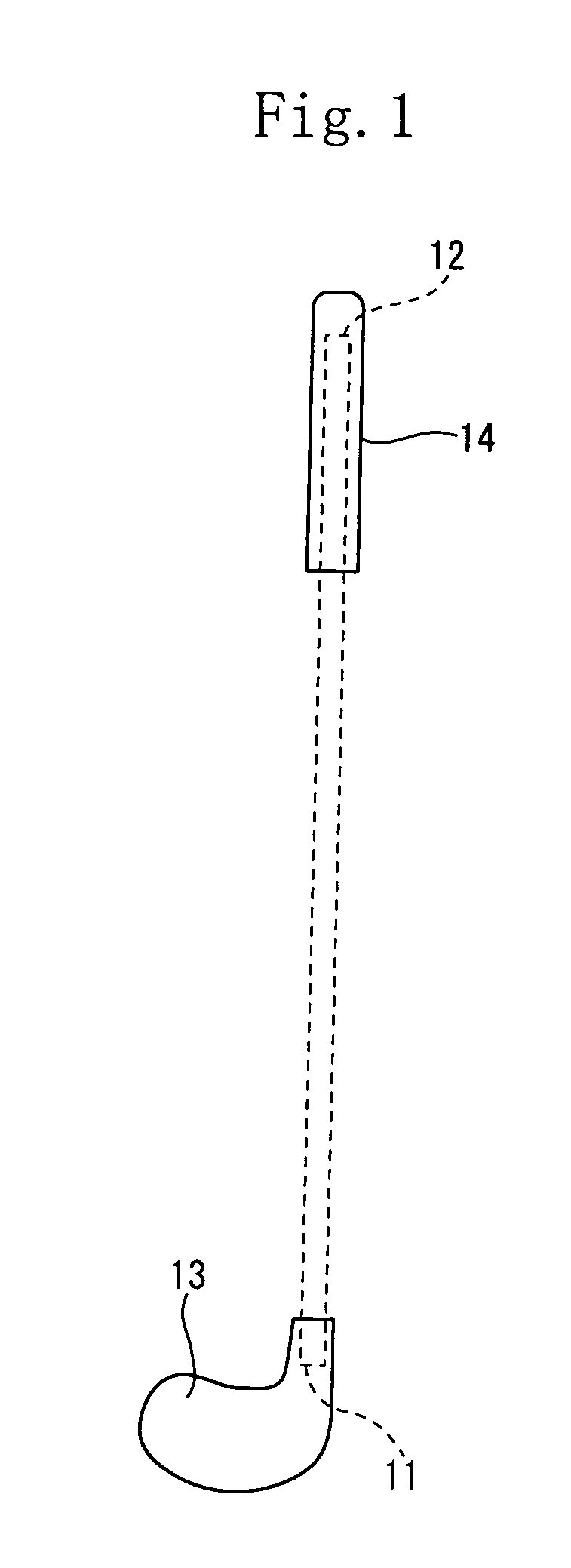
Golf club shaft

a technology for golf clubs and shafts, which is applied in the field of golf club shafts, can solve the problems of difficult to manufacture carbon nano-tubes having a uniform size, difficult to manufacture shafts with light weight, and low strength of shafts manufactured by using these methods, so as to enhance the torsional strength and torsional rigidity of shafts, and increase the weight of shafts and bending rigidities. , the effect of high energy absorption performan

Inactive Publication Date: 2009-12-08
DUNLOP SPORTS CO LTD
View PDF11 Cites 3 Cited by
  • Summary
  • Abstract
  • Description
  • Claims
  • Application Information

AI Technical Summary

Benefits of technology

[0011]The present invention has been made in view of the above-described problems. Therefore it is an object of the present invention to provide a golf club shaft that is lightweight and has a proper degree of flexibility and strength.

Problems solved by technology

But shafts manufactured by using these methods have a low strength.
Thus it is difficult to manufacture a shaft which has a light weight, a high flexibility, a high strength, and a high directional stability in hit balls.
It is difficult to manufacture the carbon nano-tubes having a uniform size.

Method used


Image

  • Golf club shaft
  • Golf club shaft
  • Golf club shaft

Examples


example 1

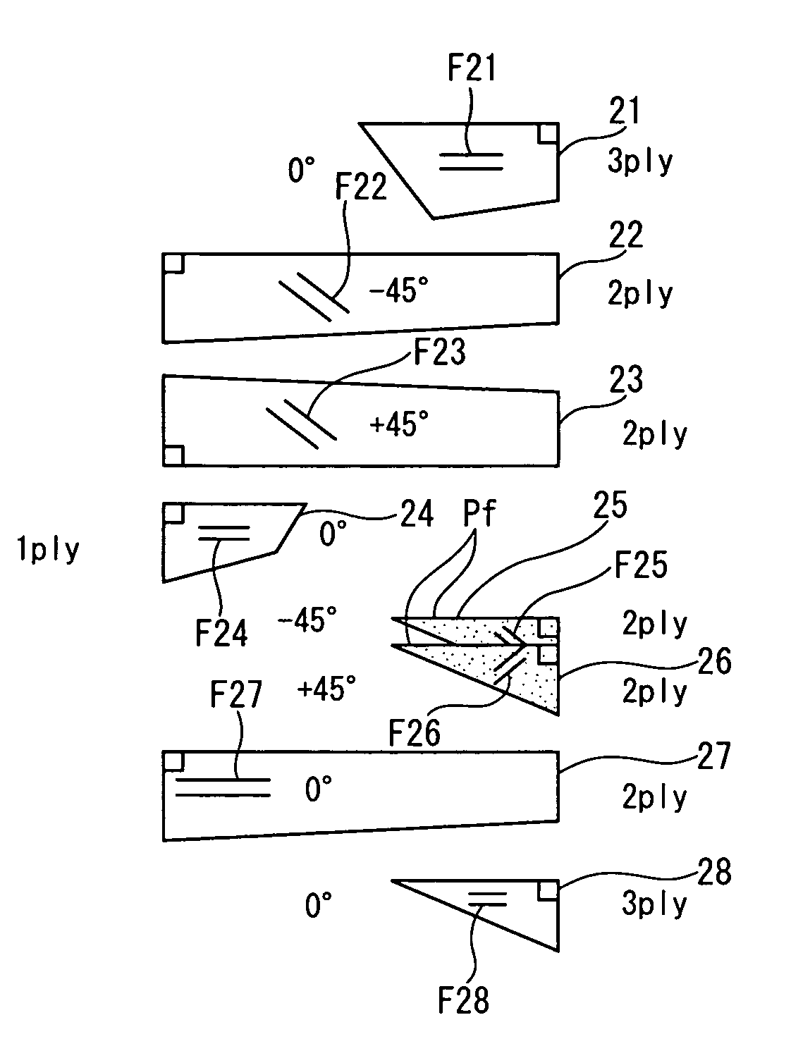
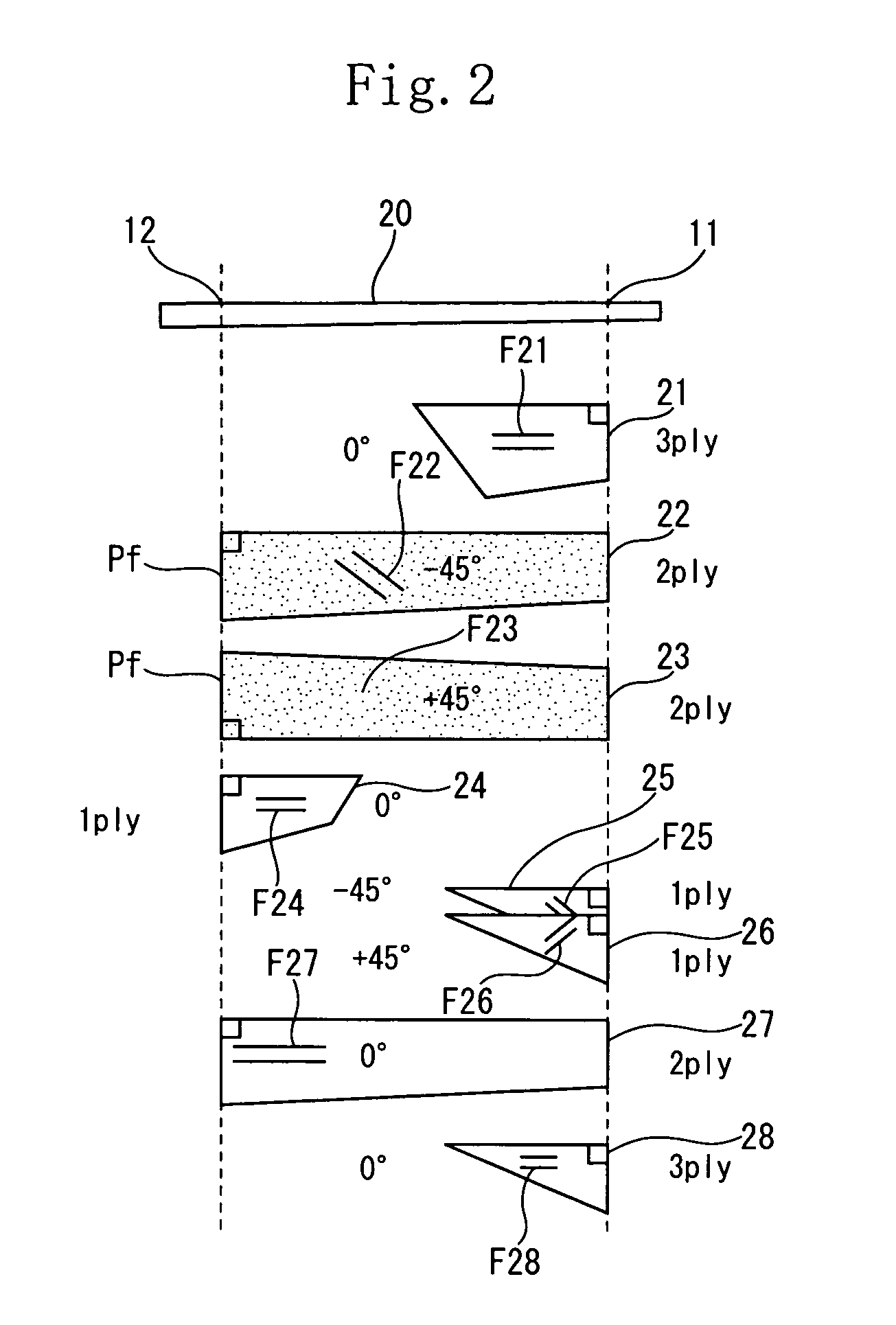
[0106]The layered construction of prepregs was identical to that of the second embodiment. More specifically, a fifth-layer prepreg 25 and a sixth-layer prepreg 26 were formed as fullerene-containing prepregs. A mandrel was wound with two turns of the prepregs 25, 26 to form fullerene-containing bias layers in only a range spaced at an interval of 300 mm from the head-side tip of the shaft. Each of the prepregs 25, 26 contains said fullerene or / and said fullerene compound at not less than 0.002 wt % of the weight of said matrix resin, namely, the epoxy resin.

[0107]The prepreg a was used as the first layer 21. The prepreg b was used as the second layer 22 and the third layer 23. The prepreg c was used as the fourth layer 24. The prepreg d was used as the fifth layer 25 and the sixth layer 26. The prepreg c was used as the seventh layer 27. The prepreg c was used as the eighth layer 28.

example 2

[0108]The shaft of the example 2 had the same prepreg-layered construction and the same content of the fullerene contained in the fullerene-containing prepreg as those of the shaft of the second embodiment. The shaft of the example 2 is different from that of the example 1 in that the content of the fullerene of each of the fifth and sixth layers was set to 0.02 wt %. In other constructions, the shaft of the example 2 was identical to that of the example 1.

example 3

[0109]The shaft of the example 3 had the same prepreg-layered construction and the same content of the fullerene of the fullerene-containing prepreg as those of the shaft of the first embodiment. More specifically, a second-layer prepreg 22 and a third-layer prepreg 23 were formed as fullerene-containing prepregs. The mandrel was wound with two turns of the prepregs 22, 23 to form the fullerene-containing bias layers over the full length of the shaft. A fifth-layer prepreg 25 and a sixth-layer prepreg 26 did not contain the fullerene. The mandrel was wound with one turn of the prepregs 25, 26. The content of the fullerene of each of the prepregs 22, 23 was set to 0.02 wt % of the weight of the epoxy resin.

[0110]The prepreg a was used as the first layer 21. The prepreg d was used as the second layer 22 and the third layer 23. The prepreg c was used as the fourth layer 24. The prepreg c was used as the fifth layer 25 and the sixth layer 26. The prepreg c was used as the seventh layer ...


PUM


Abstract

A golf club shaft composed of a laminate of prepregs. A part of the laminate is formed as a fullerene-containing bias layer BF composed of prepregs containing a matrix resin and fullerene and / or a fullerene compound contained in the matrix resin. Reinforcing fibers of the prepregs form an angle of not less than ±10° nor more than ±80° to the axis of the shaft.

Description

[0001]This nonprovisional application claims priority under 35 U.S.C. § 119(a) on Patent Application No(s). 2005-323151 filed in Japan on Nov. 8, 2005, the entire contents of which are hereby incorporated by reference.FIELD OF THE INVENTION[0002]The present invention relates to a golf club shaft. More particularly, the present invention is intended to improve the strength of a golf club shaft made of a fiber reinforced resin.DESCRIPTION OF THE RELATED ART[0003]In recent years, to allow golfers to hit golf balls at high speeds and directionally stably, the present tendency is to make a golf club head heavy and make the golf club shaft as lightweight as possible. Therefore as the material of the golf club shaft, the fiber reinforced resin such as a carbon prepreg that is lightweight and has a high specific strength and a high specific rigidity is mainly used.[0004]Owing to a low birth rate, there is a tendency for senior golfers to increase in the future. Thus there is a growing deman...

Claims


Application Information

Patent Timeline
Patent Type & Authority Patents(United States)
IPC IPC(8): A63B53/10A63B102/32B82Y99/00
CPCA63B53/10A63B59/0014A63B2209/023A63B2209/02A63B2209/00A63B60/10A63B60/06A63B60/08A63B60/0081
Inventor KUMAMOTO, TOMIO
Owner DUNLOP SPORTS CO LTD
Why Eureka
Try Eureka