Staple drive assembly

a technology of drive assembly and staples, which is applied in the direction of surgical staples, paper/cardboard containers, manufacturing tools, etc., can solve the problems of non-uniform staple formation, twisting of staple pushers in the grooved slot, and binding of staples, so as to maximize the driving of staple pushers

Active Publication Date: 2009-12-22
TYCO HEALTHCARE GRP LP
View PDF51 Cites 1714 Cited by
  • Summary
  • Abstract
  • Description
  • Claims
  • Application Information

AI Technical Summary

Benefits of technology

[0009]The actuation sled includes a base, at least one camming member and a guide member. Each camming member includes a first or leading cam wedge and a second or trailing cam wedge. The leading and trailing cam wedges are laterally and longitudinally spaced apart from one another. Spacing of the cam wedges apart, both laterally and longitudinally, creates a situation in which the staple pusher is contacted at points offset in two planes so that as the staple pusher is driven, it is controlled and driven substantially perpendicular to the tissue plane of the cartridge without rocking in any direction which would compromise driving the staple perpendicular to the tissue contacting plane. Additionally, each cam wedge includes a first drive face and a second drive face. In one embodiment, the first drive faces form first drive angles with respect to the base and second drive faces form second drive angles with respect to a plane that is substantially parallel to the base. The guide member is adapted for slidably engaging the guide channel for aligning and guiding the actuation sled as it translates through the staple cartridge. In one embodiment, first drive faces are oriented such that first drive angles may be in a range of about 30° to about 40° while the second drive faces are oriented such that second drive angles may be in a range of about 15° to about 25°.
[0011]Distal travel of the actuation sled through the staple cartridge causes the sequential engagement of the actuation sled and the staple pushers disposed in the staple cartridge. As the actuation sled moves along the longitudinal axis of the staple cartridge, the first drive faces slidably engage the first cam surfaces thereby urging each staple pusher in a generally vertical direction. As the actuation sled continues to move distally, the second drive faces slidably engage the second cam surfaces of each staple pusher to continue to drive each staple pusher in a generally vertical direction while the first drive faces disengage from the first cam surfaces. Each camming member contacts each staple pusher in at least two longitudinally spaced locations for urging each staple pusher vertically. This longitudinally staggered arrangement of the drive faces in cooperation with the complementary staggered arrangement of the cam members maximizes the longitudinal stability of the staple pusher as it moves vertically. Additionally, the first and second drive angles in cooperation with the complementary first and second receiving angles contribute to the improved longitudinal stability of each staple pusher.
[0012]In another embodiment of the present disclosure, an actuation sled includes substantially the same or similar components, but the first and second drive angles may be in a range of about 5° to about 35° while the second drive angles may be in a range of about 20° to about 55°. In another embodiment, first drive angles may be in a range of about 10° to about 30° while second drive angles may be in a range of about 25° to about 45°. In a further embodiment, first drive angles may be in a range of about 15° to about 25° while second drive angles may be in a range of about 30° to about 40°. During distal movement of the actuation sled, the first drive faces slidably engage the second cam surfaces urging each staple pusher in a generally vertical direction. As the actuation sled continues to move distally, the second drive faces engage first cam surfaces as the first drive faces disengage from the second cam surfaces. Applicants have found that providing a cam wedges with a first drive surface angle which is less than the second drive angle provides a smooth firing stroke. Similar to the previous embodiment, longitudinal stability of the staple pusher is maximized by the longitudinally staggered (i.e. spaced apart) cam members in cooperation with the complementarily staggered cam wedges. In addition, when the first drive angle is less than the second drive angle, the staple pusher contacts both drive surfaces as contact with the staple pusher transitions from contacting one drive surface to the other drive surface.
[0018]As will be appreciated from the disclosure, controlled driving of the staple pushers can be maximized by providing cam wedges which are offset both laterally and longitudinally from each other with each drive surface having a first drive angle which is less than the second drive angle.

Problems solved by technology

Several issues arise in designing staple pushers for driving one or more surgical staples.
If the forces applied to the staple pusher are not effectively balanced, there is a tendency for the staple pusher to twist within the grooved slot and / or bind against the walls of the grooved slot.
Additionally, a single point of contact between the actuation sled and the staple pusher may create a rocking point on the staple pusher which can cause the staple pusher to exit the staple cartridge in an unbalanced manner which may result in non-uniform staple formation.

Method used


Image

  • Staple drive assembly
  • Staple drive assembly
  • Staple drive assembly

Examples


Embodiment Construction

[0094]Embodiments of the presently disclosed staple drive assembly will now be described in detail with reference to the drawings, in which like reference numerals designate identical or corresponding elements in each of the several views. As used herein, the term “distal” refers to that portion of the instrument, or component thereof which is further from the user while the term “proximal” refers to that portion of the instrument or component thereof which is closer to the user.

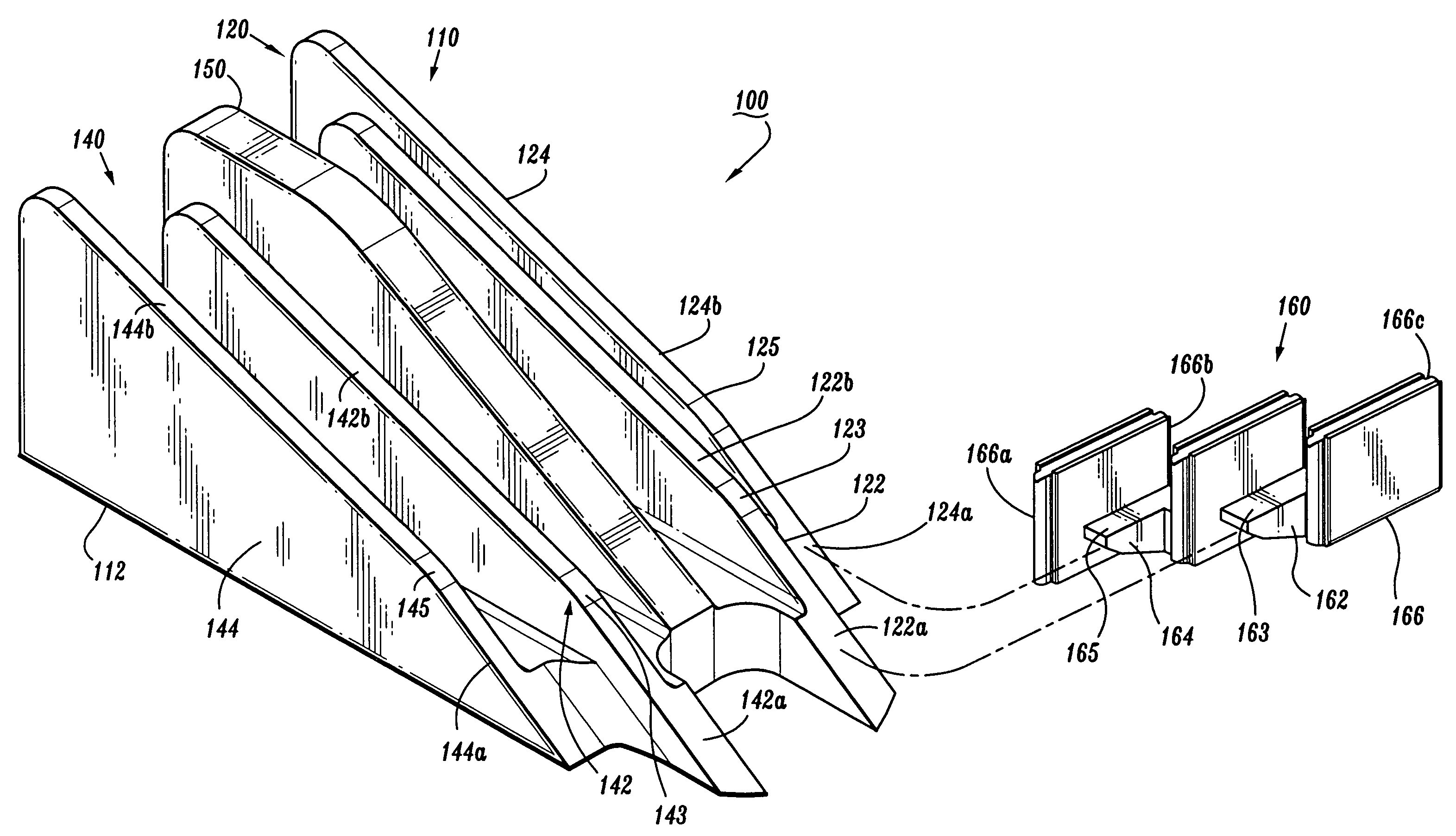
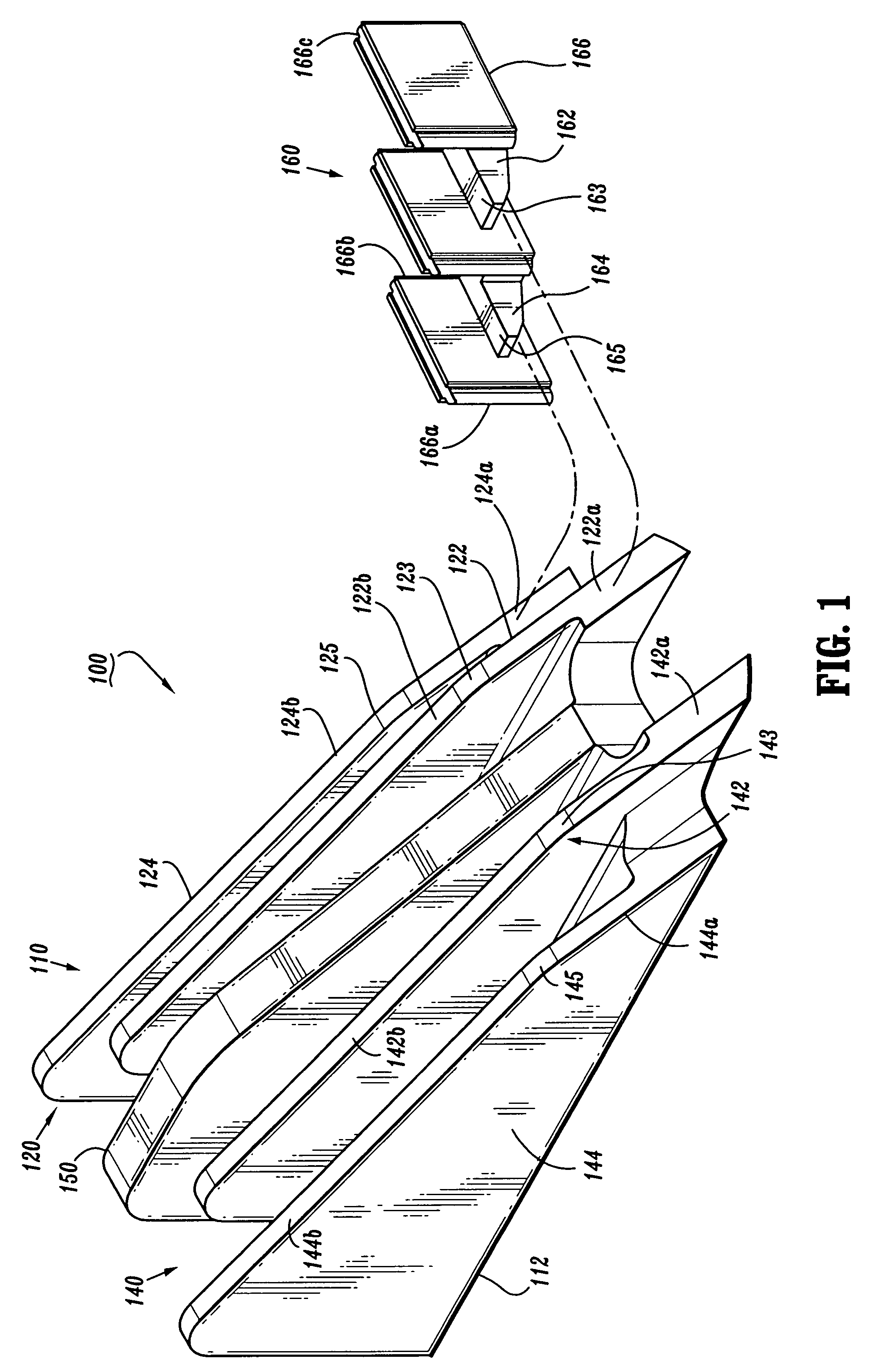
[0095]A staple drive assembly 100, in accordance with one embodiment of the present disclosure, is illustrated in FIG. 1. Staple drive assembly 100 includes an actuation sled 110 and at least one staple pusher 160. Actuation sled 110 includes a base 112, a first camming member 120, a second camming member 140, and a guide member 150. First and second camming members 120, 140 include respective first or leading cam wedges 122, 142 and respective second or trailing cam wedges 124, 144. In one embodiment, stapl...


PUM

PropertyMeasurementUnit
drive anglesaaaaaaaaaa
receiving anglesaaaaaaaaaa

Abstract

A staple drive assembly includes an actuation sled and at least one staple pusher. The staple drive assembly is adapted to fit within a staple cartridge having a plurality of staples and a corresponding number of retention slots. The at least one staple pusher includes at least one pusher plate for releasably engaging a backspan of a staple. The staple pusher may include a plurality of pusher plates that may be laterally and longitudinally spaced apart. An actuation member has at least one angled camming surface for engaging a complimentary angled surface of the at least one staple pusher. Camming engagement between the actuation member and the at least one staple pusher causes vertical movement of the at least one staple pusher. Lateral and longitudinal offset of the actuation member camming surfaces and the corresponding staple pusher following surfaces improves stability and control of the staple pusher during firing.

Description

CROSS REFERENCE TO RELATED APPLICATION[0001]This application is a continuation-in-part of U.S. patent application Ser. No. 11 / 242,761, filed Oct. 4, 2005, the entire contents of which are incorporated by reference herein.BACKGROUND[0002]1. Technical Field[0003]The present disclosure relates to stapling apparatus. More particularly, the present disclosure relates to a staple drive assembly for use in a staple cartridge of a stapling apparatus.[0004]2. Background of Related Art[0005]Surgical stapling apparatus are widely used in surgical procedures to fasten body tissue quickly and efficiently by driving fasteners, or staples into the tissue. In certain types of stapling apparatus, a drive member moves transversely to the direction the staples are to be driven. Typically, such stapling apparatus employ a number of staple pusher elements located in grooved slots of a staple cartridge and arranged end to end in rows. Under normal operation, the transversely moving drive member contacts ...

Claims


Application Information

Patent Timeline
Patent Type & Authority Patents(United States)
IPC IPC(8): A61B17/064
CPCA61B17/07207A61B17/068A61B17/0644A61B2017/0688A61B2017/07242A61B2017/07278A61B2017/07235A61B17/0682A61B17/072A61B17/105
Inventor OLSON, LEE ANNSTEARNS, RALPH
Owner TYCO HEALTHCARE GRP LP
Why Eureka
Try Eureka