

Method for block-by-block casting of concrete continuous beam bridge by using military truss shift mould
A technology of shifting formwork and truss is applied in the field of concrete continuous girder bridges cast in blocks by using military truss shifting diecasting. good effect
- Summary
- Abstract
- Description
- Claims
- Application Information
AI Technical Summary
Problems solved by technology
Method used
Image

Examples
Embodiment 1
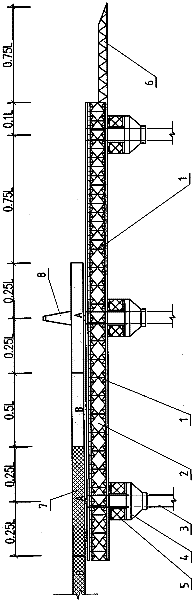
[0025] Embodiment 1: The method of using the two-hole longitudinal steel truss to move the mold and divide the hole into the concrete continuous beam bridge is as follows: Picture 1-1 with 1-2 Shown:
[0026] a. Conditions of use: In order to save the amount of steel trusses used when the construction period is not controlled, the total length of the longitudinal steel trusses 1 is 2.5L, and the process of pouring single-span box girders in A and B sections is implemented. Only one span is poured, and in order to meet the requirement of longitudinal movement and anti-overturning stability of the longitudinal steel truss 1, a guide beam 6 shall be erected on the horizontal steel truss 5 at the front end of the mold shifting.
[0027] b. Applicable span: when L≤25m, Bailey longitudinal steel truss 1 is used for the construction of moving formwork and blocks, each piece is 1.5m high, 3m long, 0.23m wide, and weighs 270kg; chord 2 [10, which can be pinned manually Knot installat...
Embodiment 2
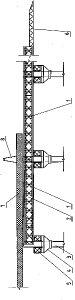
[0039] Example 2 as image 3 Shown: a method of moving concrete continuous girder bridges by using temporary piers in the middle of the span. The diameter is half of the span L of the continuous concrete beam of the whole hole, the self-weight bending moment of the continuous concrete beam can be reduced by four times, and the construction can be carried out according to the scheme of L<25m mentioned in the previous paragraph; Pier 9 adopts vertical steel pipe columns with expanded foundation, and a pair of hydraulic jacks are installed on the top of steel pipe temporary pier 9. When the concrete continuous beam has a large deflection during the construction of moving the formwork and block pouring, vertical jacks can be used to adjust it; After the hole reinforced concrete continuous beam pouring construction is completed, the steel pipe temporary pier 9 is tied up with a wire rope and dragged to a new position for reinstallation.
Embodiment 3
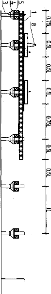
[0040] Example 3 as diagram 2-1 , 2-2 , 2-3, 2-4 and 2-5 show: a method (abbreviated as CMSS) for simultaneously pouring two-span concrete continuous girder bridges by using three-hole longitudinal steel truss moving mold blocks, when 25m
PUM
 Abstract
Description
Claims
Application Information