Extruder having variable mid-barrel restriction and adjacent high intensity mixing assembly

a technology of extruder and mid-barrel restriction, which is applied in the field of extrusion assembly, can solve the problems of not providing the higher sme and cook value desired by extrusion processor

Inactive Publication Date: 2009-12-22
WENGER MANUFACTURING INC
View PDF33 Cites 8 Cited by
  • Summary
  • Abstract
  • Description
  • Claims
  • Application Information

AI Technical Summary

Benefits of technology

[0007]The present invention overcomes the problems outlined above and provides an extrusion assembly (which may be either a single or twin screw extrusion assembly) comprising an elongated barrel having an inlet and a spaced, restricted orifice die outlet, with a mid-barrel valve assembly located along the length of the barrel and including structure for selective, variable restriction of material flow through the valve assembly. The assembly further has at least one elongated, axially flighted screw assembly within the barrel and operable to move material from the inlet, through the barrel and valve assembly and out the die outlet. This screw assembly includes a disrupting / homogenizing screw section upstream of the barrel valve assembly, wherein the disrupting / homogenizing screw section has a plurality of flighted screw parts, with at least one of the screw parts having a right-hand pitch, and at least another of the screw parts having a left-hand pitch. The combined use of a mid-barrel valve assembly together with such a disrupting / homogenizing screw section has proven to give desirable feed or food processing results.
[0008]In preferred forms, the screw parts are arranged so that adjacent ones of the screw parts have opposite pitches. Most preferably, the disrupting / homogenizing screw section is immediately adjacent the valve assembly, whereby material exiting the disrupting / homogenizing screw section flows directly into the valve assembly without encountering an additional flighted screw section(s). Also, an atmospheric vent may be provided downstream of the valve assembly, and preferably immediately adjacent the latter. Use of a vent commonly occurs in order to minimize excessive expansion in the final extrudate.

Problems solved by technology

While such expedients are common, they have not provided the higher SME and cook values desired by extrusion processors.

Method used


Image

  • Extruder having variable mid-barrel restriction and adjacent high intensity mixing assembly
  • Extruder having variable mid-barrel restriction and adjacent high intensity mixing assembly
  • Extruder having variable mid-barrel restriction and adjacent high intensity mixing assembly

Examples


example

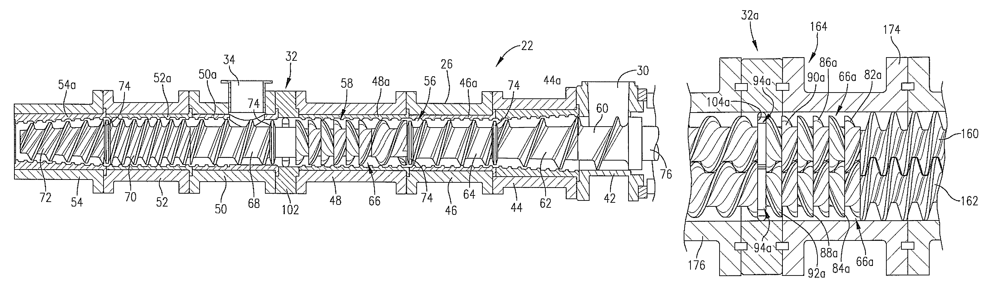
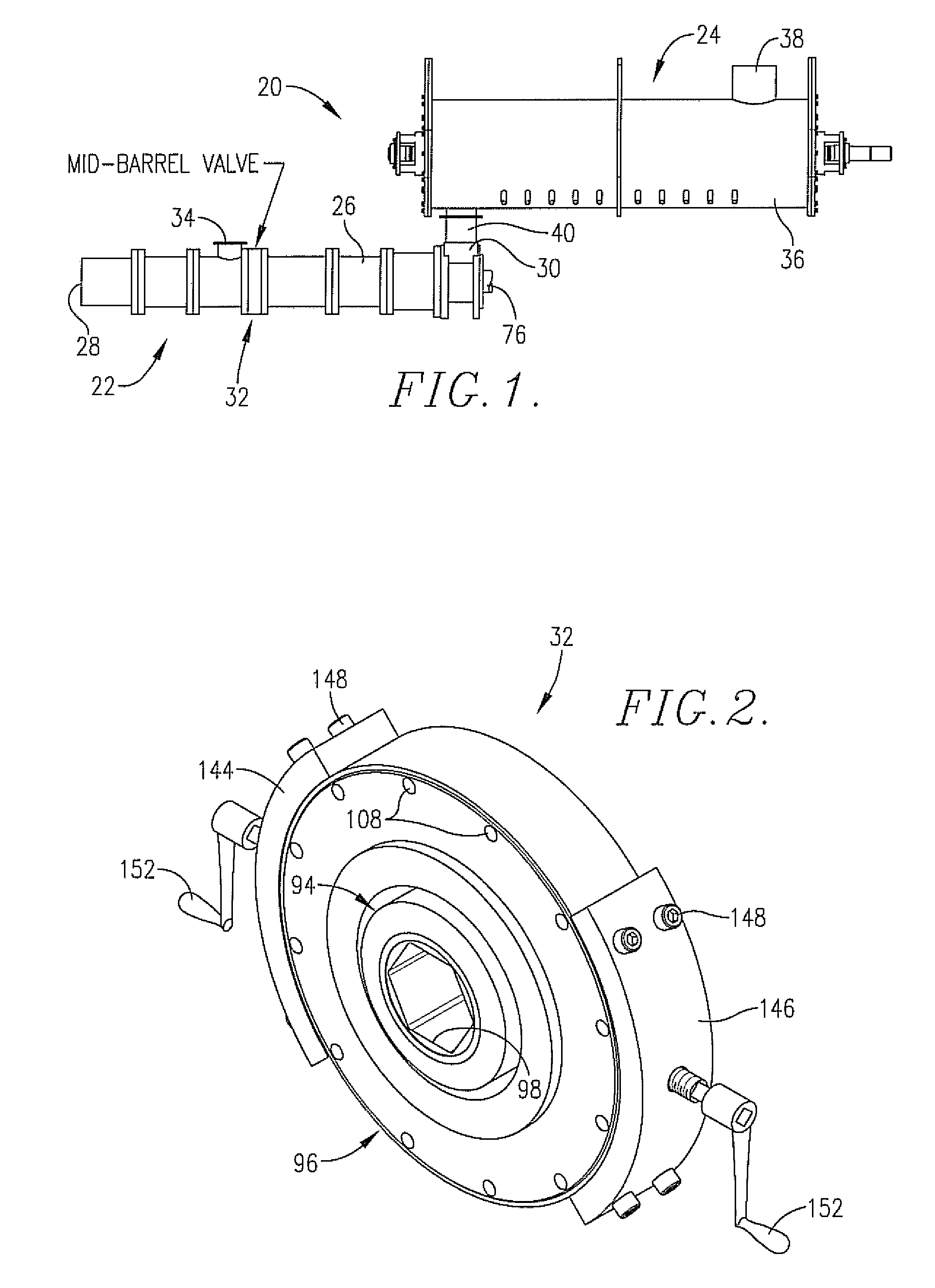
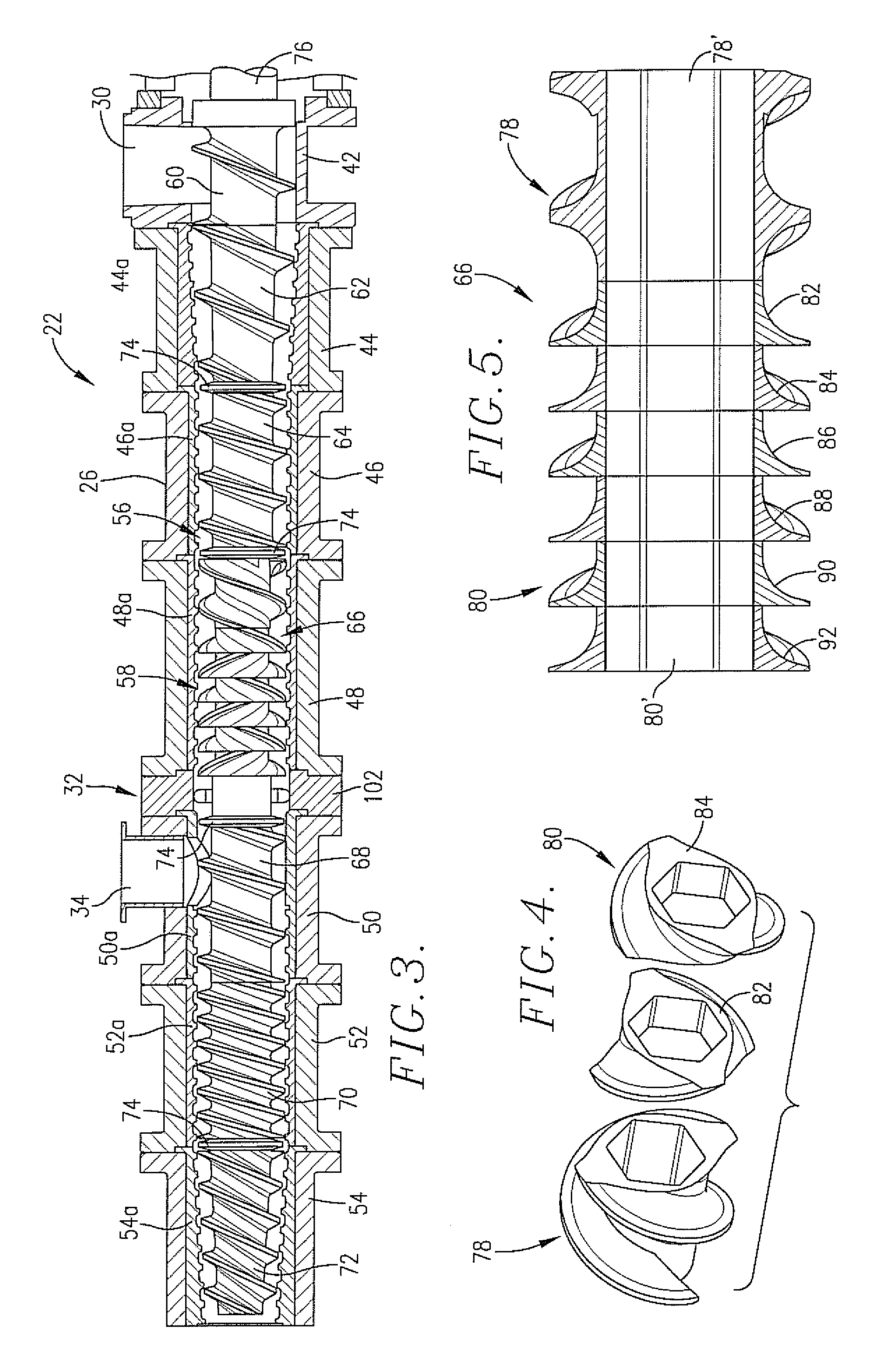
[0049]In this example, two different salmon feed recipes were processed using a standard 7-head single screw extruder setup (runs 1 and 3) versus a 7-head single screw setup identical with the standard setup except for the provision of alternating pitch disrupting / homogenizing screw parts as illustrated in FIG. 3 in the fourth head (runs 2 and 4). Each setup included a mid-barrel valve of the type illustrated in FIG. 2 between the fourth and fifth heads, with a vacuum vent immediately downstream of the valve. A standard model 16 Wenger DDC preconditioner upstream of the extruder was used in each test. The products were processed by initial preconditioning with addition of steam and water, followed by extrusion with steam and water injection. In these runs, the extruder heads were temperature-controlled by passing water through the external jackets of the heads.

[0050]The first recipe used in runs 1 and 2 comprised 19.8% by weight cereal grain, 19.6% by weight functional plant protein...


PUM

PropertyMeasurementUnit
retention timeaaaaaaaaaa
vent pressureaaaaaaaaaa

Abstract

Improved, high Specific Mechanical Energy extrusion systems (20) are provided including a single or twin extruder (22) and an upstream preconditioner (24). The extruder (22) includes an elongated barrel (26) with at least one elongated, axially flighted, rotatable screw assembly (58) therein. The barrel (26) includes a mid-barrel variable restriction valve assembly (32), and the screw assembly (58) has a disrupting / homogenizing screw section (66) therein upstream of the valve assembly (32). The screw section (66) includes a plurality of alternating pitch screw parts (82-92). Preferably, the barrel (26) also has an atmospheric vent (36) downstream of the valve assembly (32).

Description

BACKGROUND OF THE INVENTION[0001]1. Field of the Invention[0002]The present invention is broadly concerned with improved extrusion assemblies used for the processing of animal feeds or human foods and giving enhanced Specific Mechanical Energy values as compared with conventional extruder designs. More particularly, the invention is concerned with such extrusion assemblies wherein the extruder barrel is equipped with a mid-barrel valve assembly permitting selective, variable flow of material therethrough, together with a disrupting / homogenizing screw section upstream of the valve assembly. In further preferred aspects of the invention an atmospheric vent is provided downstream of the variable valve assembly.[0003]2. Description of the Prior Art[0004]Extrusion systems are commonly used in the production of human foods and animal feeds. Broadly speaking, there are two types of extrusion systems, namely single screw and twin screw systems. As the names imply, single screw extruders inc...

Claims


Application Information

Patent Timeline
Patent Type & Authority Patents(United States)
IPC IPC(8): B29B7/48B29B7/74B29C48/06B29C48/395B29C48/76
CPCB29B7/481B29C47/6075B29C47/0871B29C47/38B29C47/60B29C47/0825B01F7/00425B29C47/0016B29C48/06B29C48/2564B29C48/268B29C48/395B01F27/1144
Inventor ROKEY, GALEN J.PLATTNER, BRIAN S.
Owner WENGER MANUFACTURING INC
Why Eureka
Try Eureka