
Force transfer assemblies

a technology of force transfer and assembly, which is applied in the direction of hoisting equipment, nuclear elements, nuclear engineering, etc., can solve the problems of short travel range, increased construction costs, and increased fuel expenses, and adversely affect longevity

Inactive Publication Date: 2010-01-05
THE BOEING CO
View PDF11 Cites 8 Cited by
  • Summary
  • Abstract
  • Description
  • Claims
  • Application Information

AI Technical Summary

Benefits of technology

This solution enables the efficient transfer of forces while protecting the fibers from compressive stresses, allowing for the use of lighter and more compact cable assemblies that maintain high tensile strength without compromising the structural integrity.

Problems solved by technology

Fluid forces such as the air resistance forces encountered by vehicles such as aircraft and boats may result in higher fuel expenses and shorter travel ranges.
Fluid forces such as wind loads may affect the stability of structures such as bridges and may therefore increase construction costs and adversely affect longevity.
Transverse forces that tend to compress or flatten a cable can compromise the effective tensional strength of the cable.
Such compromising transverse forces may be of concern when using even time-honored materials such as steel cables, but are often of heightened concern when using modern fibers.
The molecular structure of some typical such fibers provide impressive tensile strength along their lengths but are vulnerable to damage and failure when subjected to forces transverse to their lengths such as shear forces and transverse compression forces.
A problem arises, however, when strong cables are needed.
Undesirable damage and even a cascading failure of a cable may result beginning with the failures of inner-most layers.
Such solutions, however, entail using cables that are heavy and that have large cross-sectional areas.
Such solutions are therefore less than optimal and, in a sense, defeat many of the very goals underlying the development of modern fibers which were developed to be lightweight and compact.

Method used


Image

  • Force transfer assemblies
  • Force transfer assemblies
  • Force transfer assemblies

Examples


Embodiment Construction

[0035]The present invention now will be described more fully hereinafter with reference to the accompanying drawings, in which some, but not all embodiments of the invention are shown. Indeed, the invention may be embodied in many different forms and should not be construed as limited to the embodiments set forth herein; rather, these embodiments are provided so that this disclosure will satisfy applicable legal requirements. Like numbers refer to like elements throughout.

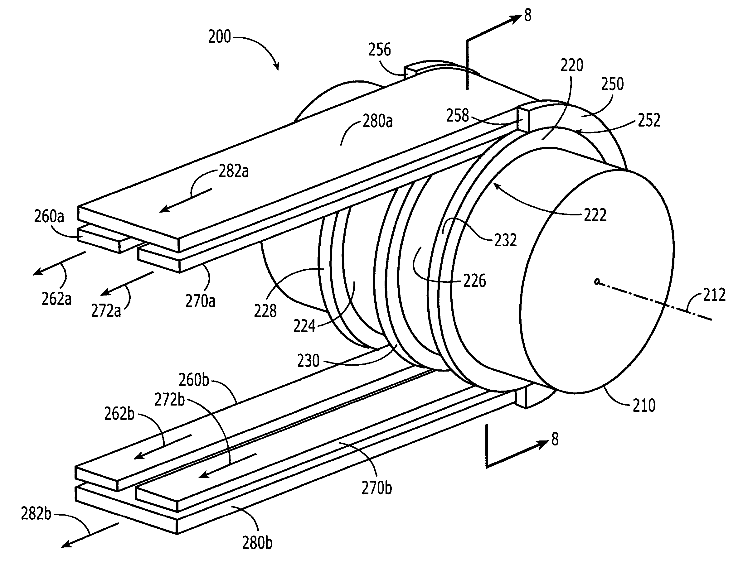
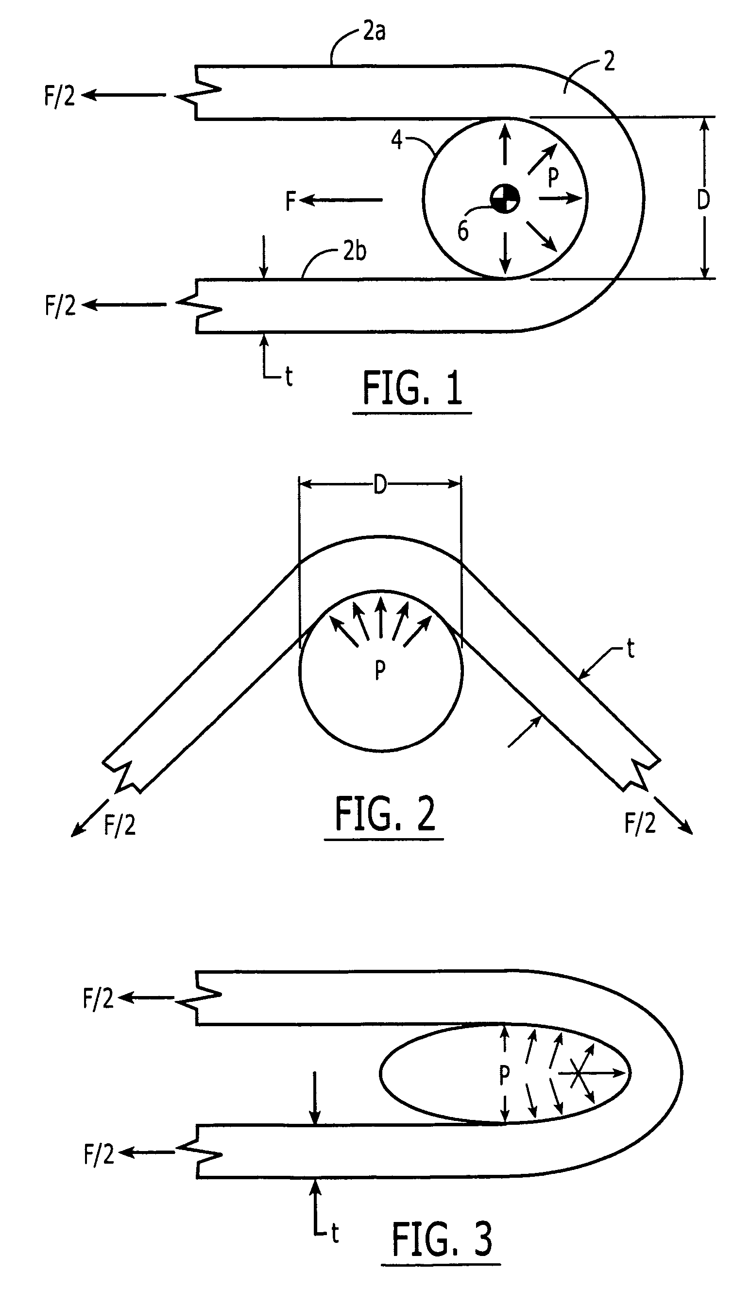
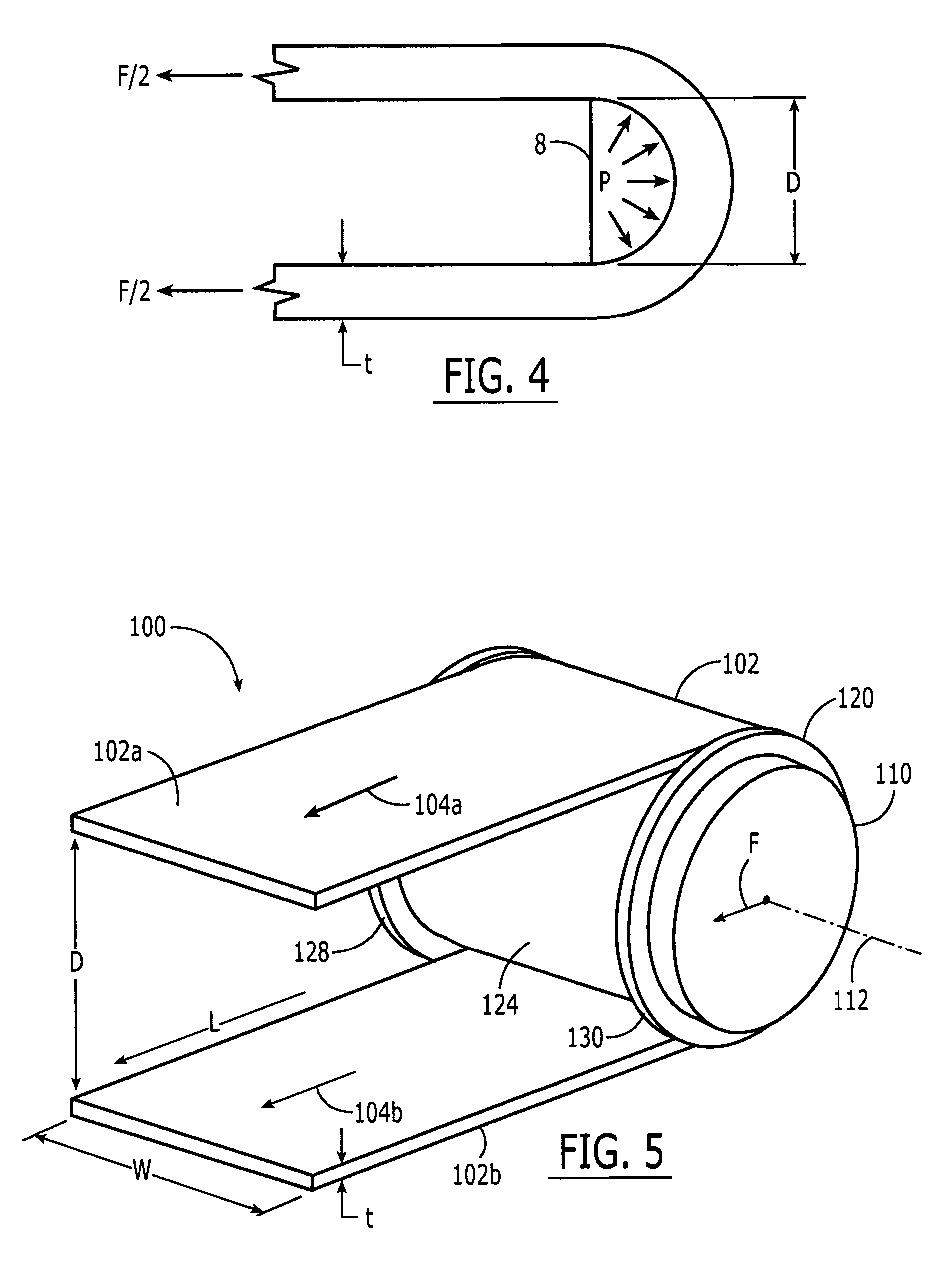
[0036]A theoretical approach to understanding the transfer of forces from a tensioned member such as a cable to a receiving structure such as a cylindrical member is described herein with references to Equations 1-7 and FIGS. 1-4. These equations, figures and any underlying theories and approximations are described to promote an understanding of concepts underlying the developments of the various embodiments of the invention that are described herein with reference to FIGS. 5-16. The present invention, having many ...


PUM


Abstract

Force transfer assemblies are provided for transferring forces from tensionable members to receiving structures. The assemblies may include nested thimbles that transfer respective forces from respective tensionable members to receiving structures such as cylindrical members. An outer thimble may transfer force from an outer tensioned member to a receiving structure without causing compression of an inner tensioned member. For example, the outer thimble may transfer forces by way of the inner thimble or to a boss of the receiving structure. Forces from a tensioned member or assembly of tensioned members may be distributed along a cylindrical member by a thimble having a convex bearing surface or by spaced thimbles disposed along the cylindrical member.

Description

FIELD OF THE INVENTION[0001]Embodiments of the present invention relate generally to force transfer assemblies that transfer forces from tensioned members such as cables to receiving structures. More particularly, embodiments of the invention relate to thimbles disposed between tensionable members and receiving structures such as rigid cylindrical members.BACKGROUND OF THE INVENTION[0002]Cables, belts, and straps are utilized as tensional elements in bracing systems found in aircraft, boats, cranes, winches, bridges and various other mobile and static structures such as buildings and signage structures. Naturally, light weight assemblies of cables and connecting elements are typically preferred in order both to save expenses in their constructions and to maximize payload capabilities of a structure. Compact assemblies are typically preferred in order to maximize the useful space within a structure and in order to minimize the overall size of a structure. Compact assemblies are also ...

Claims


Application Information

Patent Timeline
Patent Type & Authority Patents(United States)
IPC IPC(8): B66D3/08
CPCF16G15/12F16G11/146D07B1/185F16G11/00
Inventor RAWDON, BLAINE K.
Owner THE BOEING CO
Learn More