Battery connector having polarized arrangement

a technology of polarized arrangement and battery connector, which is applied in the direction of electrical equipment, cell components, and incorrect coupling prevention, etc., can solve the problem of difficult wear of the curved surface, and achieve the effect of reducing manufacturing cost, improving molding efficiency, and reducing shake of the battery received

Inactive Publication Date: 2010-01-05
HON HAI PRECISION IND CO LTD
View PDF10 Cites 4 Cited by
  • Summary
  • Abstract
  • Description
  • Claims
  • Application Information

AI Technical Summary

Benefits of technology

[0007]It is an object of the present invention is to provide a battery connector provided with polarized arrangement so as to prevent incorrect insertion of a battery to be inserted therein.
[0008]An aspect of the present invention provides a battery connector, comprises an insulative housing comprising mounting surface and a top surface opposite to the mounting surface. A receiving chamber is defined in the housing from the top surface with first and second conductive terminals spatially arranged within the chamber. The chamber features at least a rounded corner for conforming to a rounded edge of a battery to be inserted so as to prevent the battery from being inserted incorrectly.
[0010]The battery connector according to the embodiments of the present invention has the continuous curved surfaces, and the curved surface is tangential to the inner wall. Therefore, a transition area between the curved surface and the inner wall is smooth but does not have a slit or a sharp angle, so as to simply configuration of a die and improve molding efficiency during inject-molding process, thereby reducing manufacturing cost. Furthermore, the curved surface can better cooperate with a shape of the battery so that the curved surface is difficult to be worn. In addition, at an aspect of the present invention, the curved surfaces extend to the inserting surface from the receiving chamber which is distant from a bottom of the receiving chamber a height of at most half the length of the receiving chamber. Thus, when the battery is mounted onto the battery connector, two sides of the battery can still cooperate with the curved surfaces tightly so as to reduce shake of the battery received in the receiving chamber and further keep steady electrical connection.

Problems solved by technology

Furthermore, the curved surface can better cooperate with a shape of the battery so that the curved surface is difficult to be worn.

Method used


Image

  • Battery connector having polarized arrangement
  • Battery connector having polarized arrangement
  • Battery connector having polarized arrangement

Examples


Embodiment Construction

[0017]Hereinafter, in order to make the above objects, features and advantages to be easily understood, embodiments of the present invention will be described in detail with reference to the accompanying drawings.

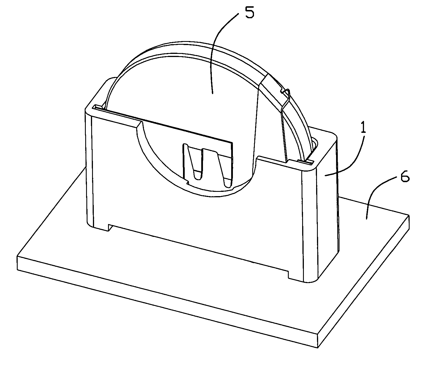
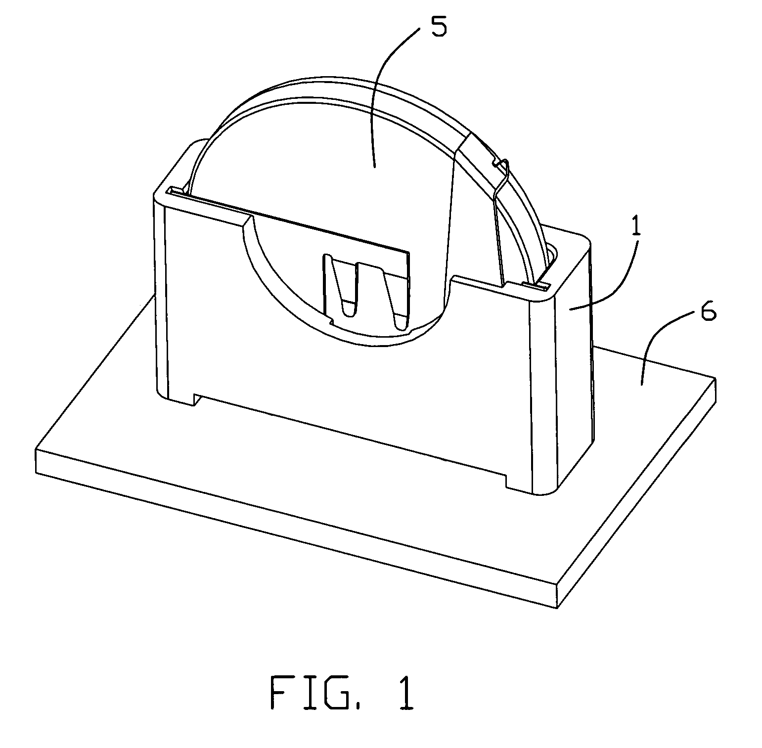
[0018]FIG. 1 is a perspective view of an battery connector which is in use in accordance with a first embodiment of the present invention, wherein a battery is mounted therein. Referring to FIG. 1, a battery connector 1 in accordance with a first embodiment of the present invention is configured to establish an electrical connection between a battery 5 and a printed circuit board 6.

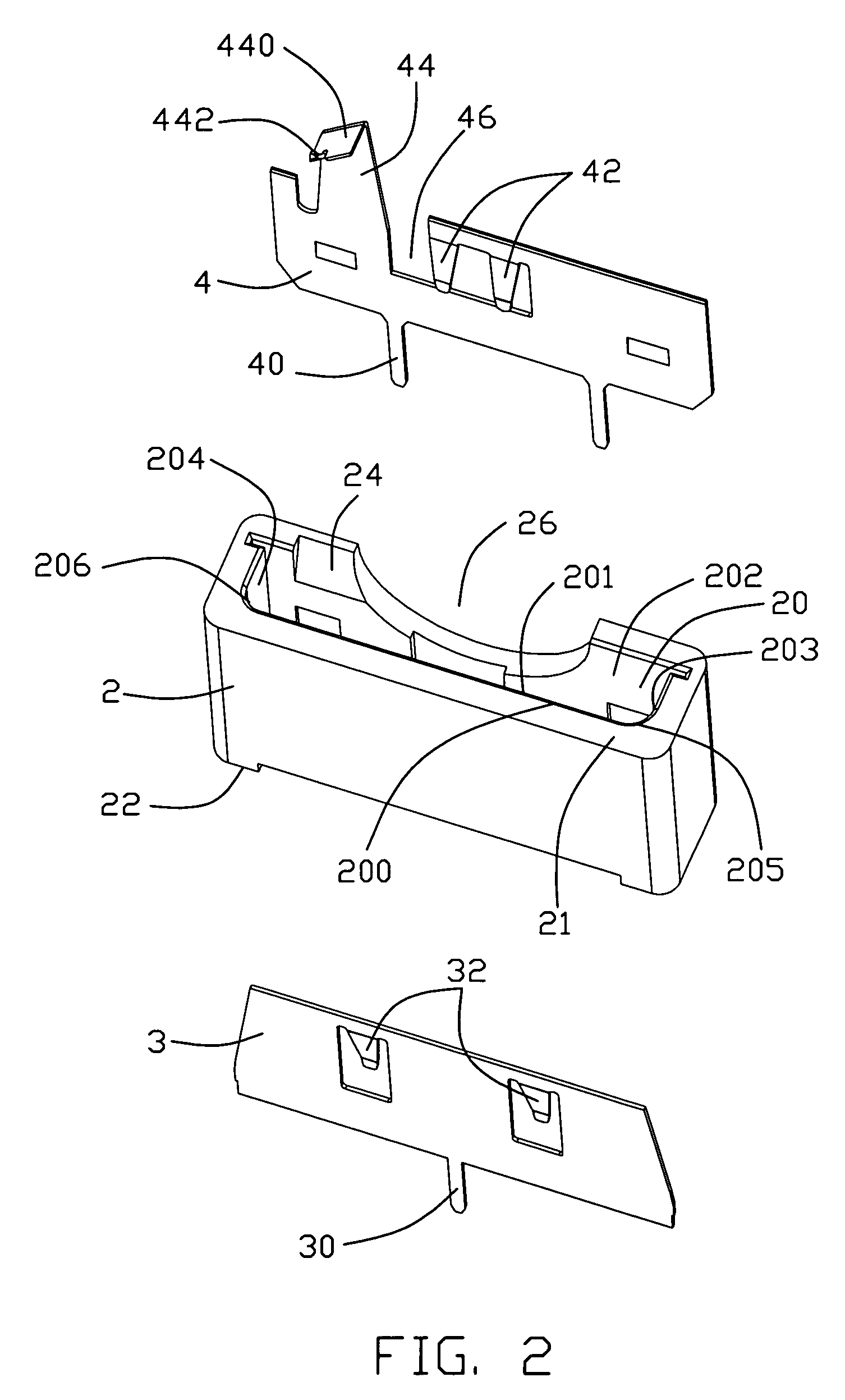
[0019]Referring to FIG. 1 to FIG. 3, the battery connector 1 comprises an insulative housing 2 and a first conductive terminal 3 and a second conductive terminal 4 respectively received in the insulative housing 2. The insulative housing 2 has an inserting surface 21 and a mounting surface 22 opposite to the inserting surface 21. A receiving chamber 20 having a certain length is disposed in insul...


PUM

PropertyMeasurementUnit
conductiveaaaaaaaaaa
heightaaaaaaaaaa
resilientaaaaaaaaaa

Abstract

A battery connector comprises an insulative housing comprising mounting surface and a top surface opposite to the mounting surface. A receiving chamber is defined in the housing from the top surface with first and second conductive terminals spatially arranged within the chamber. The chamber features at least a rounded corner for conforming to a rounded edge of a battery to be inserted so as to prevent the battery from being inserted incorrectly. The rounded corner has a curve surface tangent to two inner side walls of the chamber.

Description

BACKGROUND OF THE INVENTION[0001]1. Field of the Invention[0002]The present invention relates to a battery connector, and more particularly to a batter connector provided with polarized arrangement so as to prevent incorrect insertion of a battery to be inserted therein.[0003]2. Background of the Invention[0004]Electrical connectors are widely applied to the electronic industry. For example, the electrical connector is used for electrical connection and signal transmittance between elements, assemblies or systems of an electronic device. The electrical connector is a necessary and basic component for constituting a whole system.[0005]Chinese Utility Patent No. CN2466796 issued to Deyou He on Dec. 19, 2001 (hereinafter, referred to as He's '796 patent), discloses an battery connector for holding a button battery therein. Referring to the figures in the '796 patent, the battery connector comprises an insulative housing 1, a positive terminal 2 and a negative terminal 3. The insulative...

Claims


Application Information

Patent Timeline
Patent Type & Authority Patents(United States)
IPC IPC(8): H01R3/00H01M50/202H01M50/262
CPCH01R13/64H01M2/1022Y02E60/10H01M50/202H01M50/262
Inventor CHEN, DE-JINHSIAO, YU-SAN
Owner HON HAI PRECISION IND CO LTD
Why Eureka
Try Eureka