Shielded twisted-pair conductor connector

A connector and conductor technology, applied in the field of electronic connection devices, can solve the problems of difficult installation process, small electrical clearance, poor matching, etc., and achieve the effect of strong anti-interference shielding ability, improved insulation performance, and good sealing performance.

Active Publication Date: 2021-03-19
NUCLEAR POWER INSTITUTE OF CHINA
View PDF18 Cites 3 Cited by
  • Summary
  • Abstract
  • Description
  • Claims
  • Application Information

AI Technical Summary

Problems solved by technology

[0005] The technical problem to be solved by the present invention is: the matching between the existing multi-core connector and the shielded twisted-pair conductor assembly is poor, the electrical gap is small, and the installation process is difficult. The present invention provides a shielded twisted-pair conductor assembly to solve the above problems. Conductor connectors are suitable for electrical penetrations in nuclear power plants, engineering test reactors and decommissioned nuclear facilities. They are used to realize the connection between shielded twisted-pair cables and shielded twisted-pair conductors, and meet functional requirements such as strong radiation resistance and anti-electromagnetic radiation interference. , with good electrical performance and sealing performance

Method used


Image

  • Shielded twisted-pair conductor connector
  • Shielded twisted-pair conductor connector

Examples


Embodiment 1

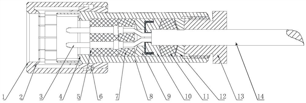
[0042] This embodiment presents a shielded twisted-pair conductor connector, including a plug and a connector. The plug includes a cylindrical plug housing II8, pin contacts 3, plug insulators 5, plug insulating mounting plates 7 and plug seals. Inside the plug housing II8 along the axial direction, pin contacts 3 , plug insulators 5 , plug insulation mounting plates 7 and plug seals are arranged in sequence. The plug is used to install one end of the flexible shielded twisted pair cable 14; after one end of the flexible shielded twisted pair cable 14 passes through the plug seal, the core wires of one end of the flexible shielded twisted pair cable 14 are fixed on the plug insulation mounting plate 7 at intervals , and the free end of the core wire is welded to the pin contact piece 3; the welding part between the free end of the core wire and the pin contact piece 3 is contained in the plug insulator 5; and the outer wall of one end of the flexible shielded twisted pair cable...

Embodiment 2

[0046] Further improvement on the basis of Example 1, the specific design of the seal of the plug and the structure of the seal of the joint is as follows:

[0047] The plug seal includes bushing I9, bushing II10, washer II11, washer III12 and bushing 13. In the axial direction of the plug housing II8 and away from the plug insulation mounting plate 7, a bushing I9 and a bushing II10 are arranged in sequence; the core wire located outside the plug insulation mounting plate 7 passes through the center of the bushing I9 and the bushing II10 position, and is fixed by the reverse compression of bushing I9 and bushing II10. In the axial direction of the plug housing II8 and away from the bushing II10, the gasket II11 and the gasket III12 are arranged in sequence, and the shaft sleeve 13 is screwed to the port of the plug housing II8; by tightening the shaft sleeve 13, the shaft sleeve 13 squeezes Compression gasket II11 and gasket III12 are filled through the elastic deformation o...

Embodiment 3

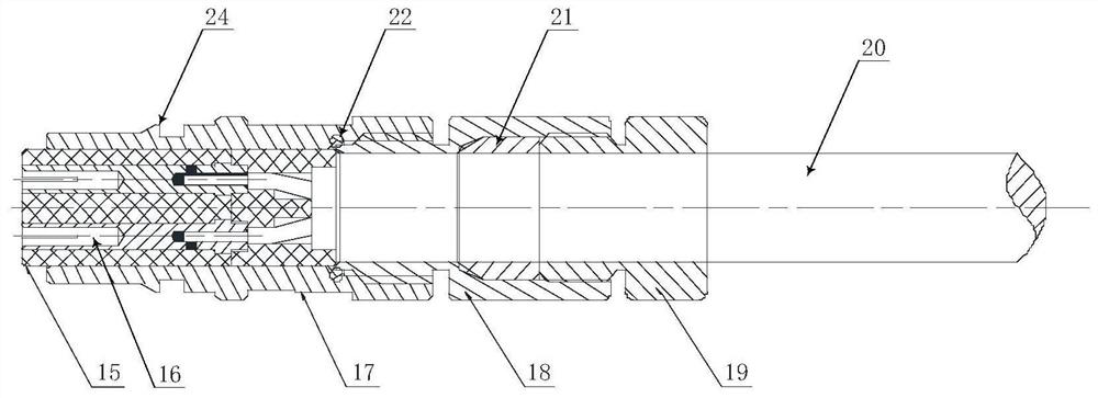
[0050] Further improvement on the basis of Embodiment 2, the plug also includes a plug shell I1 and a gasket I4; one end of the plug shell I1 is sleeved on one end of the plug shell II8 provided with pin contacts 3; a socket contact 16 is provided One end of the joint housing 17 is inserted into the plug housing I1, and the end face of the plug housing I1 is in sealing contact with the end face of the plug housing II8 through the gasket I4. The outer wall of the joint housing 17 is provided with a multi-tooth annular structure as the claw 24 along the circumference; The inner wall of the plug housing I1 is provided with a keyway extending in the axial direction, and the outer wall of the joint housing 17 is provided with a guide key extending in the axial direction, and the guide key is slidably fitted to the keyway.


PUM


Abstract

The invention discloses a shielding twisted-pair conductor connector. The connector comprises a plug and a joint; the plug is electrically connected with a flexible shielding twisted-pair cable core through welding, and the joint is electrically connected with a rigid shielding twisted-pair conductor through welding; the plug and the joint are electrically connected through elastic contact connection of the jack contact piece and the pin contact piece. The insulating layer is designed in a split manner and is divided into the mounting plate and the insulator; according to the shielding twisted-pair conductor joint, the wire cores are independently fixed on the mounting plate, the defects of high core wire bending difficulty, small twisted-pair core wire gap and mutual welding influence areeffectively overcome, the welding spots are contained in the insulator, the creepage distance can be effectively increased, and the insulating property of the shielding twisted-pair conductor joint is improved. The connector provided by the invention has the advantages of excellent structure, good sealing performance, stable electrical performance, strong anti-interference shielding capability and the like, and is a special shielding twisted-pair connector capable of meeting special requirements of radiation resistance, aging resistance and the like.

Description

technical field [0001] The invention relates to the technical field of electronic connection devices, in particular to a shielded twisted-pair conductor connector. Background technique [0002] A large number of electronic and electrical systems and equipment are usually configured in nuclear power plants and engineering test reactors, and various signal interconnections are realized through transmission and control cables between the equipment. Shielded twisted-pair conductor assembly, as one of the new conductor assemblies of third-generation nuclear power plant electrical penetrations, is a widely used transmission medium. Its twisted-pair structure can increase the immunity of transmission lines and prevent the leakage of transmission signals. The shielding layer wrapped outside has a better suppression effect on higher frequency electromagnetic fields, and has good electrical performance and electromagnetic shielding performance. The shielded twisted-pair conductor joi...

Claims


Application Information

Patent Timeline
Patent Type & Authority Applications(China)
IPC IPC(8): H01R13/40H01R13/6591
CPCH01R13/40H01R13/6591
Inventor 邱新媛王广金陈青周天周缘赵雨恒王江武周寒侯睿王新宇
Owner NUCLEAR POWER INSTITUTE OF CHINA
Why Eureka
Try Eureka