

Method for controlling a robot arm, and robot for implementing the method
a robot arm and robot arm technology, applied in the direction of electrical programme control, program control, instruments, etc., can solve the problems of high probability of collision in the use of medical robots, inability to perform preoperative planning sufficiently detailed and flexible corresponding to actual events, and inability to predict the environment. the effect of collision risk and/or the effect of force acting
Active Publication Date: 2010-01-12
DEUTSCHES ZENTRUM FUER LUFT & RAUMFAHRT EV +1
View PDF11 Cites 240 Cited by
- Summary
- Abstract
- Description
- Claims
- Application Information
AI Technical Summary
Benefits of technology
[0007]It is an object of the present invention to provide a method for controlling a robot arm which reduces the risk of collisions and / or the forces acting on openings. Further, it is an object of the invention to provide a device for practicing the method.
[0018]Further, the operator can command robot movements by impressing forces on the robot arm (haptic interaction). This possibility of interacting with the entire robot arm by manual guiding, based in this case on the control methods outlined above (this type of interaction is also referred to as soft robotics), is an important approach to the Implementation of robots, especially in environments difficult to predict: in particular, it allows for the use of robots in medical applications, since avoiding collisions by a preoperative planning of trajectories is not always practicable because of the dynamic and hardly predictable scenario at the operating table. If, for example, a collision between the robot and the environment is imminent, the robot may be given a collision-free configuration also by a non-specialist (e.g., a surgical nurse) using the above described methods, without having to interrupt the surgical procedure. In this sense, the above described operating method is ideal for the use of robots in medical applications.
[0019]It is particularly preferred to correspondingly control two joints such that the torque acting on two joints is controlled to substantially zero. Preferably, these are two adjacent joints connected through a connecting element, e.g., a web-shaped component or the like. In particular, the joints controlled according to the invention are two joints that are closest to an environment element on which no forces are exerted, and which can generate forces in the tangential plane at the penetration point. In minimally invasive applications in medikine, the present invention thus considerably reduces the occurrence of forces at the opening in the patient, with no significant forces occurring anymore because of the control, so that preferably no damages occur at the opening site. The joints controlled according to the invention are joints whose torques would generate a bearing force of the instrument at the penetration point of the inner edge of the opening in the patient.
[0021]The present invention thus allows to maintain both the base and the end effector of the robot arm at a fixed position and a fixed orientation, by using a robot arm with a redundant number of joints, i.e. redundant kinematics. Here, the base of the robot arm is a first, possibly stationary, element of the robot arm. The end effector is the last member of the robot arm, e.g., supporting the robot hand, a medical device etc. At the same time, the present method allows to move an end effector with a fixed position and orientation through different arm configurations, i.e., to perform a zero space movement. It is thus possible to perform certain end effector movements with a kinematically redundant robot or a robot with redundant joints, which movements may be, for example, movements to be performed during a surgical operation, while an elbow of the robot arm is moved to other positions to avoid collisions.
[0024]Therefore, the present method for controlling a robot arm offers the following advantages:
[0027]zero moment control of at least two robot joints in the manipulation of laparoscopic instruments to reduce the transmission of translational forces vertical to the instrument axis at the trocar point in minimally invasive surgery.
Problems solved by technology
With robots intended to interact with a dynamic environment, if a suitable modelling of the environment is impossible or can be achieved only with great efforts, mere position control or mere force control will yield only unsatisfactory results in view of avoiding collisions.
A predictive modelling of an environment is very hard to realize, especially in medical applications.
The events occurring during medical procedures, which are not or only very vaguely predictable, and the lack of space prevailing there lead to a high probability of collision in the use of medical robots.
On the one hand, no preoperative planning that would be sufficiently detailed and flexible corresponding to the actual events can be performed to avoid collisions, and on the other hand, the close interaction of the robot with the patient and a practitioner makes it impossible to define necessary safety areas (workcell) as is done in industrial robotics.
An evasion by the elbow, while the robot end effector maintains its position and orientation, is not possible.
A corresponding problem also exists in other applications, for example in industrial applications, in which a robot is used in limited spaces and / or sensitive components and the like are present in the vicinity of the robot.
The above described problem exists especially if an instrument, such as a tool, a camera or the like, carried by a robot arm is passed through an opening into a device such as a turbine.
Method used
View moreImage
Smart ImageViewing Examples

Examples
first embodiment
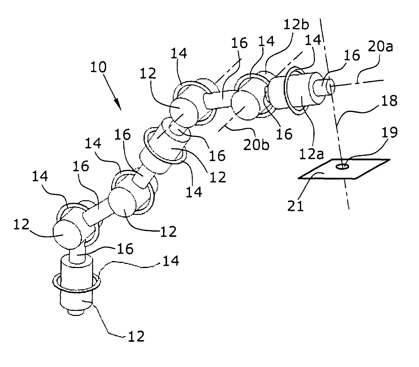
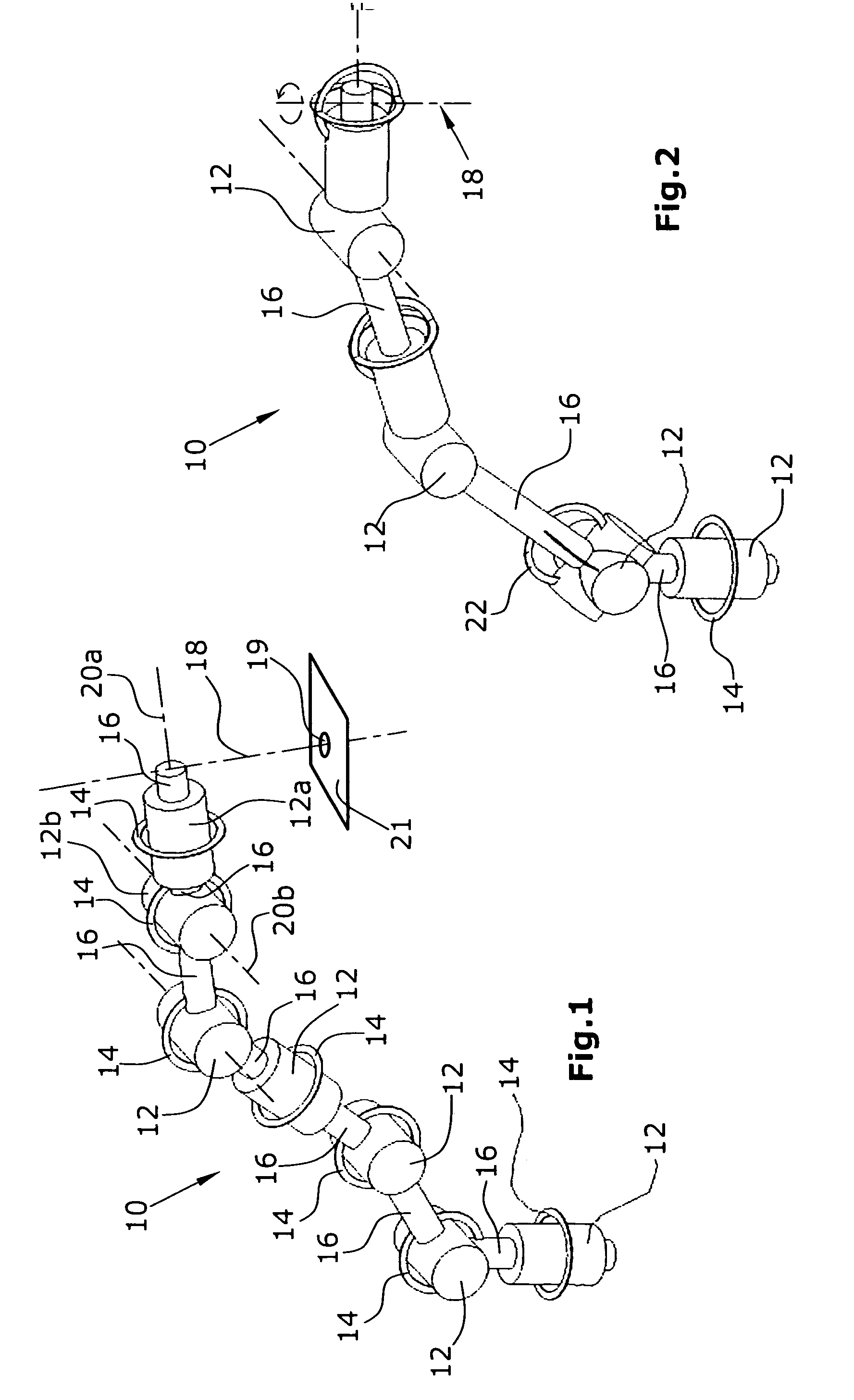
[0035]FIG. 1 is a schematic general illustration of a robot arm according to a robot arm,
second embodiment
[0036]FIG. 2 is a schematic general illustration of a robot arm according to a robot arm,
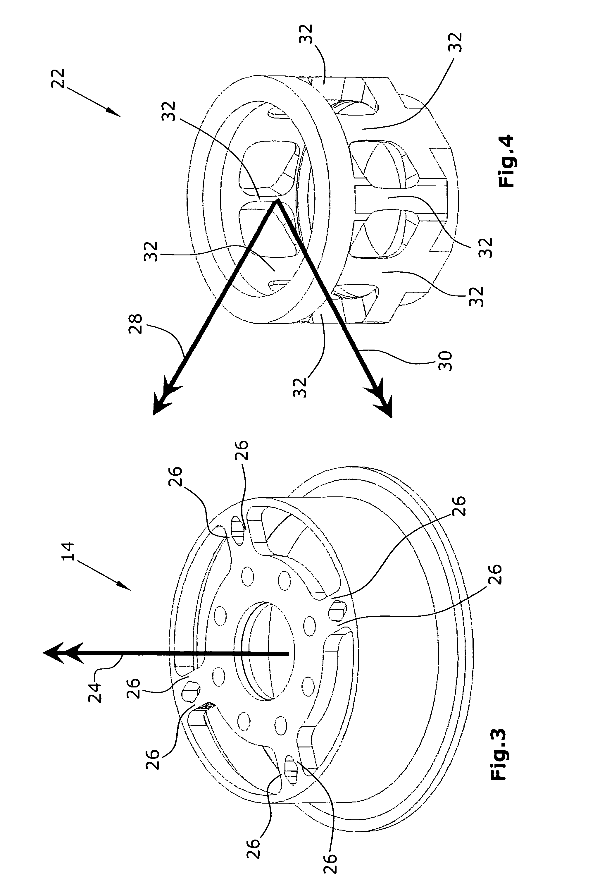
[0037]FIG. 3 is a schematic perspective view of a single axis torque sensor adapted to be used in a robot arm illustrated in FIG. 1,
[0038]FIG. 4 is a schematic perspective view of a multi-axis torque sensor adapted for use in a robot arm illustrated in FIG. 2, and
[0039]FIGS. 5-7 show examples of flow charts for zero moment controls according to the invention, based on impedance control, admittance control and impedance projection.
Login to View More PUM
 Abstract
In a method for controlling a robot arm, which is particularly suitable for use in medical applications, a robot arm (10) with a redundant number of joints is used. A torque acting in at least one joint (12a, 12b) is sensed. By means of a control device, the torque acting in this joint (12a, 12b) is controlled to become substantially 0.
Description
BACKGROUND OF THE INVENTION[0001]The present application claims the priority of German Patent Application No. 10 2005 054 575.0-15 which is herewith incorporated herein by reference.FIELD OF THE INVENTION[0002]The invention refers to a method for controlling a robot arm which is particularly suitable for use in medical applications. Further, the invention refers to a robot for implementing the method.DESCRIPTION OF RELATED ART[0003]With robots intended to interact with a dynamic environment, if a suitable modelling of the environment is impossible or can be achieved only with great efforts, mere position control or mere force control will yield only unsatisfactory results in view of avoiding collisions. A predictive modelling of an environment is very hard to realize, especially in medical applications.[0004]The events occurring during medical procedures, which are not or only very vaguely predictable, and the lack of space prevailing there lead to a high probability of collision in...
Claims
Login to View More Application Information
Patent Timeline
 Patent Type & AuthorityPatents(United States)
IPC IPC(8): G05B19/4061G05B19/33
CPCA61B19/22B25J9/1633B25J9/1643B25J13/085A61B2019/2292A61B2019/464A61B2090/064A61B34/70A61B34/76G05B2219/40599
InventorALBU-SCHAFFER, ALINOTT, CHRISTIANHAGN, ULRICHORTMAIER, TOBIAS
OwnerDEUTSCHES ZENTRUM FUER LUFT & RAUMFAHRT EV